Adaptive virtual terrain texturing

Today I would like to talk about a new algorithm implemented in Nebula, and this one is for making beautiful terrain at scale! Our implementation of this algorithm is extracted from the little concrete information provided by Ka Chen in his great presentation in 2015 at GDC, where he presented a novel way of doing virtual texturing in order to increase resolution dynamically, instead of the otherwise static resolution of ordinary virtual texturing.

Motivation

Before we get down to brass tacks, just a little motivation as to why on earth we would go through this work and not just do ordinary virtual texturing using the GPU sparse binding API (which Nebula also supports). Well, the answer is resolution. And if your question is why we can’t do the texture splatting (sampling the materials) at runtime instead of going about storing it in some texture cache, well the answer is that in order to add small detail like decals on the terrain, we would have to render many many decal boxes every frame and it would be expensive, while this method caches that result for sampling every frame.

In our solution, which follows the one from FarCry 4, we want a 64k maximum theoretical resolution SubTexture, which over an area of 64×64 meters yields 1024 pixels per meter. We use a fixed tile size of 256×256 pixels, which means the previous statement can also be reformulated as a resolution per tile, in which case one tile will cover 0.25 meters squared at the highest resolution, and the whole SubTexture, meaning 64 meters squared at the lowest resolution.

Overview

The algorithm can be summarized into a few abstract steps, we will then go through each step and have a look at the implementation. These steps include both CPU and GPU work, but they are presented in the order in which a programmer would approach it.

Setup

The first thing we need to do is set everything up. This step consists of the following – divide the world into 64×64 meter regions to each a SubTexture gets assigned. We will discuss the details of the SubTexture later, but for now, let’s just say it requires a world position in the range [-half world size, half world size] if oriented around 0, an indirection texture offset which can be initialized to FFFFFFF, a maximum LOD level float and an unsigned number of tiles, which can also be initialized to FFFFFFFF.

We also need an indirection texture, which in our case is 2048×2048 pixels and with a mip chain. The mip chain should meet the requirements for the maximum amount of tiles in a SubTexture, such that at the highest mip, a SubTexture represents only a single indirection pixel. So, for 256 pixel tiles, it would mean the number of mips is 8. We also have our physical texture caches which is an albedo, material and normals, at 8192×8192 standard size, or 8448×8448 padded size (explained later). The physical caches are not mipped.

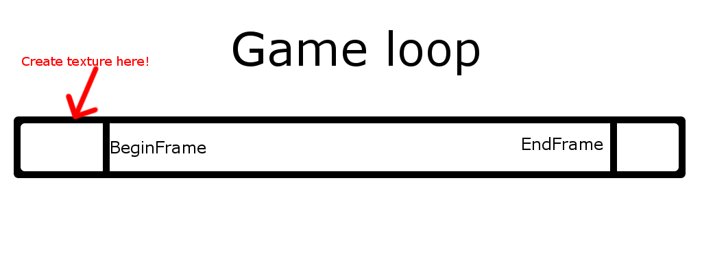
We also need to render the lowres callback. This is a texture used to render pixels for which we have no SubTextures covering them, because they are too far away. This is done with a simple screen space pass and a shader which is more or less equivalent with the tile update shader.

Our solution differs form Ka Chens solution and the follow-up solution from Ghost Recon Wildlands with how we output our pages. In the first solution, a buffer was attached and written to, in Ghost Recon Wildlands they used a 3D texture (which sounds a bit wasteful) to map page coordinate XY to the pixel in a texture plane, and the mip as the texture plane selector. In our solution, we use a buffer of indirection buffer statuses, which utilize atomic operations to decide whether or not a page has been already produced or not, and if it hasn’t we output it directly to our page buffer.

		uint index = mipOffset + pageCoord.x + pageCoord.y * mipSize;
		uint status = atomicExchange(PageStatuses[index], 1u);
		if (status == 0x0)
		{
			uvec4 entry = PackPageDataEntry(1u, subTextureIndex, lowerMip, pageCoord.x, pageCoord.y, subTextureTile.x, subTextureTile.y);

			uint entryIndex = atomicAdd(PageList.NumEntries, 1u);
			PageList.Entry[entryIndex] = entry;
		}

Here we calculate the buffer index (which is mipped, thus the offset and size modifications to the index calculation), we use atomic exchange with the page status, and if 0, we add it to the page output! This way, we don’t need to clear the buffer, nor do we have to implement a second pass to extract the data from this pass!

We need a buffer to store the page statuses used in the Terrain Prepass, which should map to a texture. Therefore, we have to make a buffer big enough to capture all mips, and also generate a list of mip sizes and mip buffer offsets such that we can emulate this being a mipped texture on the GPU. We avoid any indirection data on the CPU side, because of reasons related to copying and rearranging subtexture regions.

uint offset = 0;

terrainVirtualTileState.indirectionMipOffsets.Resize(IndirectionNumMips);
terrainVirtualTileState.indirectionMipSizes.Resize(IndirectionNumMips);
for (uint i = 0; i < IndirectionNumMips; i++)
{
	uint width = IndirectionTextureSize >> i;
	uint height = IndirectionTextureSize >> i;
		terrainVirtualTileState.indirection[i].Fill(IndirectionEntry{ 0xF, 0xFFFFFFFF, 0xFFFFFFFF });

	terrainVirtualTileState.indirectionMipSizes[i] = width;
	terrainVirtualTileState.indirectionMipOffsets[i] = offset;
	offset += width * height;
}

Because of alignment wasting memory if we use arrays of single floats or integers for constant buffers in GLSL, we opted to store these values in ivec4s using the following method:

for (SizeT j = 0; j < terrainVirtualTileState.indirectionMipOffsets.Size(); j++)
{
	uniforms.VirtualPageBufferMipOffsets[j / 4][j % 4] = terrainVirtualTileState.indirectionMipOffsets[j];
	uniforms.VirtualPageBufferMipSizes[j / 4][j % 4] = terrainVirtualTileState.indirectionMipSizes[j];
}

Later in the GPU code, you will see how we get this values back by making a similar operation.

Runtime

  1. Read back data from Terrain Prepass – CPU
    1. Setup tile update jobs for tiles that should be deleted
    2. Setup tile update jobs for tiles that should be rendered
    3. Prepare indirection buffer updates
  2. Update SubTexture buffer – CPU
    1. Based on camera distance to the world space region occupied by a SubTexture, calculate the resolution it should have (explained in detail later)
    2. Calculate number of tiles from resolution, each tile is 256 pixels in size
    3. If SubTexture changed resolution, allocate a new indirection texture region for the new resolution, and deallocate the old
    4. If SubTexture increased in size, copy the whole region of indirection values to the new region, and shift the mip down such that we only write to mips 1..x and avoid 0
    5. If SubTexture decreased in size, copy whole region from mips 0..x-1 to new region
  3. Copy buffers – CPU/GPU Transfer
    1. Copy SubTextures from old regions to new regions if changed
    2. Copy indirection pixels from buffer to texture
    3. Copy from staging subtexture buffer to GPU buffer
  4. Clear entries – GPU – Compute
  5. Render Terrain Prepass – GPU/Render
    1. Updates page entry buffer
  6. Copy page entries to CPU-readable buffer to be used in 1. – GPU/Transfer
  7. Render page tiles – GPU/Render

SubTexture

Given the overview above, it is time to go through what a SubTexture is. Imagine that we want our 64k resolution for a 64×64 meter area. For a world of size, let’s say 8192, we would need an 8mi total texture! Even with sparse resources, the biggest possible resource is 16k on Nvidia, and 32k on AMD, so that is immediately out of the question. However, we will talk about usage of sparse resources a bit later…

So think of it like this: We pretend like we have an 8mi texture, but only on the CPU side. We already have our world split into 64×64 meter regions, so we can think of each 64×64 meter region as a smaller virtual texture within our 8mi texture. This is what we refer to as a SubTexture, it is a virtual texture within the virtual texture :D. Think of the maximum resolution, like 64k for a tile of the highest resolution, as the theoretical size of a texture, which you will see won’t be fully utilized.

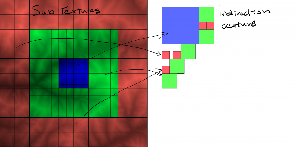
Based on the camera distance to that region, we decide how many actual physical texture tiles should be represented by that region. In the highest resolution case, where we have a 64k resolution, we have 256×256 tiles. These tiles can be found in two places, first in a 256×256 block of pixels in the indirection texture, and as scattered 256×256 pixel tiles in the three physical caches. So each tile occupies 1 pixel in the indirection texture, and a 256×256 tile in the physical caches. And SubTextures closer to the camera uses more indirection pixels, and therefore more texture tiles, hence can provide a higher resolution for nearby pixels.

Illustration of the sub textures on a heightmap. To the left we see sub textures with differing tile counts, and on the right we see the indirection pixels that they occupy. One indirection pixel points to a 256×256 pixel texture tile. Blue means highest resolution (most tiles) and red means lowest resolution (fewest tiles)

Now you might think: hold on, so if we have 256×256 indirection pixels for the highest resolution SubTexture, and each tile is 256×256 pixels, that would mean a 256*256 x 256*256 texture, which is astronomical! Well, on top of all this complexity, we will also introduce mipmaps! Each SubTexture occupies a block of indirection pixels, but as we mentioned before, the indirection texture is actually mipmapped, meaning we actually have one block for each mip level, all the way down to where a SubTexture only represents a single indirection pixel. This also means that each tile is rendered to represent a certain mip, so for a 256×256 tile at mip 0, a tile covers 0.25 meters of the world, but at mip 8, it covers a whooping 64 meters. For a tile covering only 1×1 tiles, it only has a single mip.

Calculating LODs

You might have gathered by now that one of the things we have to do manually in this algorithm is to calculate the LODs. We need to calculate LODs ourselves for two things, first to determine how many tiles a SubTexture should use, and then when rendering the terrain on the GPU, decide which mip a pixel needs so we can mark the page at the proper mip as being resident. Our formula is rather straight forward:

		// control the maximum resolution as such, to get 10.24 texels/cm, we need to have 65536 pixels (theoretical) for a 64 meter region
		const uint maxResolution = SubTextureTileWorldSize * 1024;

		// distance where we should switch lods, set it to every 10 meters
		const float switchDistance = 2.0f;

		// mask out y coordinate by multiplying result with, 1, 0 ,1
		Math::vec4 min = Math::vec4(subTex.worldCoordinate[0], 0, subTex.worldCoordinate[1], 0);
		Math::vec4 max = min + Math::vec4(64.0f, 0.0f, 64.0f, 0.0f);
		Math::vec4 cameraXZ = Math::ceil(cameraTransform.position * Math::vec4(1, 0, 1, 0));
		Math::vec4 nearestPoint = Math::minimize(Math::maximize(cameraXZ, min), max);
		float distance = length(nearestPoint - cameraXZ);

		// if we are outside the virtual area, just default the resolution to 0
		uint resolution = 0;
		if (distance > 300)
			goto skipResolution;

		// at every regular distance interval, increase t
		uint t = Math::n_max(1.0f, (distance / switchDistance));

		// calculate lod logarithmically, such that it goes geometrically slower to progress to higher lods
		uint lod = Math::n_min((uint)Math::n_log2(t), (IndirectionNumMips - 1));

		// calculate the resolution by offseting the max resolution with the lod
		resolution = maxResolution >> lod;

	skipResolution:

		// calculate the amount of tiles, which is the final lodded resolution divided by the size of a tile
		// the max being maxResolution and the smallest being 1
		uint tiles = resolution / PhysicalTextureTileSize;

Two constants here to take in mind, SubTextureTileWorldSize is set to 64 and represents the world size a SubTexture takes. IndirectionNumMips represents the amount of mips in the indirection texture, which we earlier figured out was 8. What this code is doing is that it is calculating the resolution of the SubTexture, and then converts it to a number of tiles. This is then used to determine the resolution for this SubTexture during this frame.

Let’s move on to the first GPU loop! Yes, there are two loops…

Clearing

The clear pass is rather intuitive, but for the sake of it, let’s explain exactly what it is doing.

[local_size_x] = 1
shader
void
csTerrainPageClearUpdateBuffer()
{
	PageList.NumEntries = 0u;
}

Just set the amount of entries in the entry output list

Mip

Remember the LOD calculation for the SubTexture? On the GPU it is slightly different. There, we do the following:

// convert world space to positive integer interval [0..WorldSize]
vec2 worldSize = vec2(WorldSizeX, WorldSizeZ);
vec2 unsignedPos = worldPos.xz + worldSize * 0.5f;
uvec2 subTextureCoord = uvec2(unsignedPos / VirtualTerrainSubTextureSize);

// calculate subtexture index
uint subTextureIndex = subTextureCoord.x + subTextureCoord.y * VirtualTerrainNumSubTextures.x;
if (subTextureIndex >= VirtualTerrainNumSubTextures.x * VirtualTerrainNumSubTextures.y)
	return;
TerrainSubTexture subTexture = SubTextures[subTextureIndex];

// if this subtexture is bound on the CPU side, use it
if (subTexture.tiles != 0xFFFFFFFF)
{
	// calculate LOD
	const float lodScale = 4 * subTexture.tiles;
	vec2 dy = dFdy(worldPos.xz * lodScale);
	vec2 dx = dFdx(worldPos.xz * lodScale);
	float d = max(1.0f, max(dot(dx, dx), dot(dy, dy)));
	d = clamp(sqrt(d), 1.0f, pow(2, subTexture.maxLod));
	float lod = log2(d);
	...
}
...

Let’s walk through what is happening… First thing we do is to convert the pixel coordinate to be in the [0..WorldSize] range. Using that, we select which SubTexture (remember, 64×64 meter area) this pixel is in. We check if the SubTexture is valid by checking if it has tiles. Then, we use the partial derivative of x and y for the world position, scaled by the amount of tiles the SubTexture has (the range of these values is like we said before, [1..256]) multiplied by a constant factor of 4 which just seemed to work well. That difference is used as a distance to our pixel in order to determine the slope, which is then clamped to not exceed the maximum LOD for this SubTexture. The max LOD is determined based on the amount of tiles in the SubTexture, so a SubTexture of 256 tiles has 8 as the max LOD, while a SubTexture of 1 tile has 0 as the max LOD.

Binning the pages

The next stage of the shader is to bin the pages. Following from the code before inside the inner condition, we do the following:

// calculate pixel position relative to the world coordinate for the subtexture
vec2 relativePos = worldPos.xz - subTexture.worldCoordinate;

// the mip levels would be those rounded up, and down from the lod value we receive
uint upperMip = uint(ceil(lod));
uint lowerMip = uint(floor(lod));

// calculate tile coords
uvec2 subTextureTile;
uvec2 pageCoord;
vec2 dummy;
CalculateTileCoords(lowerMip, subTexture.tiles, relativePos, subTexture.indirectionOffset, pageCoord, subTextureTile, dummy);

// since we have a buffer, we must find the appropriate offset and size into the buffer for this mip
uint mipOffset = VirtualPageBufferMipOffsets[lowerMip / 4][lowerMip % 4];
uint mipSize = VirtualPageBufferMipSizes[lowerMip / 4][lowerMip % 4];

uint index = mipOffset + pageCoord.x + pageCoord.y * mipSize;
uint status = atomicExchange(PageStatuses[index], 1u);
if (status == 0x0)
{
	uvec4 entry = PackPageDataEntry(1u, subTextureIndex, lowerMip, pageCoord.x, pageCoord.y, subTextureTile.x, subTextureTile.y);

	uint entryIndex = atomicAdd(PageList.NumEntries, 1u);
	PageList.Entry[entryIndex] = entry;
}

// if the mips are not identical, we need to repeat this process for the upper mip
if (upperMip != lowerMip)
{
	...
}
...

Here, we first calculate the relative position of this SubTexture in world space. This is used to determine a SubTexture relative distance for the tile this pixel will be binned inside. We also calculate an upper mip and lower mip, such that we capture both mips that will be used when sampling. The CalculateTileCoords function is implemented as such:

void
CalculateTileCoords(in uint mip, in uint maxTiles, in vec2 relativePos, in uvec2 subTextureIndirectionOffset, out uvec2 pageCoord, out uvec2 subTextureTile, out vec2 tilePosFract)
{
	// calculate the amount of meters a single tile is, this is adjusted by the mip and the number of tiles at max lod
	vec2 metersPerTile = VirtualTerrainSubTextureSize / float(maxTiles >> mip);

	// calculate subtexture tile index by dividing the relative position by the amount of meters there are per tile
	vec2 tilePos = relativePos / metersPerTile;
	tilePosFract = fract(tilePos);
	subTextureTile = uvec2(tilePos);

	// the actual page within that tile is the indirection offset of the whole
	// subtexture, plus the sub texture tile index
	pageCoord = (subTextureIndirectionOffset >> mip) + subTextureTile;
}

This function is meant to take in a position relative to the SubTexture in world space, that is, if a SubTexture is at coordinates (-256, -256) in world space, then a pixel at (-256, -256) would have relativePos (0, 0). The argument mip is the mip provided by the calculation above, maxTiles is the amount of tiles a SubTexture is providing at mip 0, and subTextureIndirectionOffset is the offset in the indirection texture where this SubTexture resides. The output is the pageCoord, which is the indirection texture space coordinate for this page. Accompanied by this variable is subTextureTile, which is the tile index for this pixel inside the SubTexture. Going back to the function calling this one, we use these values to calculate the index of the tile which we are updating, by using the mip offsets and mip size from the Setup phase, the calculation is a simple 2D to 1D index conversion to know which indirection pixel should be affected, and therefore which page should be updated. Like mentioned before, we use atomics to synchronize the writes to the PageEntry list, which has a cost but is much cheaper than having a clear and extraction pass.

Read back

Okay, so now we are done with the heavy lifting on the GPU side for this frame, but we will be generating work from a previous frame to update tiles on this frame! Sounds confusing? Well because we are buffering frames, the read back for this frame is at least N buffers old, so any tile updates we do now might actually already be out of view, but because of the nature of buffering there really is no way around this, unfortunately.

When reading back the data, we get what we produced from the shader and, if you noticed before the data on the GPU is packed, so we first need to unpack it. The packing is a way to reduce the amount of memory being passed over the PCI bus when reading back, so it’s important to keep it as small as possible. However, this can be contended and optimized later, for example removing the pageCoords and calculate them on the CPU side.

		uint status, subTextureIndex, mip, pageCoordX, pageCoordY, subTextureTileX, subTextureTileY;
		UnpackPageDataEntry(updateList[0].Entry[i], status, subTextureIndex, mip, pageCoordX, pageCoordY, subTextureTileX, subTextureTileY);

		// the update state is either 1 if the page is allocated, or 2 if it used to be allocated but has since been deallocated
		uint updateState = status;
		uint index = pageCoordX + pageCoordY * (dims.width >> mip);
		IndirectionEntry& entry = terrainVirtualTileState.indirection[mip][index];

We get the indirection entry by using the page coords and mip produced by the GPU. This is actually all the info we need, now all we have to do is to allocate pages or deallocate pages from the physical texture caches, produce tile update jobs and we are done!

One important thing to note here is that there is a code path for the read back information which does the following:

				TerrainSubTexture& subTexture = subTextures[subTextureIndex];
				float metersPerTile = SubTextureTileWorldSize / float(subTexture.tiles >> entry.mip);

This uses the SubTexture buffer which the GPU assumed was resident at the time of these page updates, and as per subTextureIndex, it becomes clear we need to use the SubTextures that were in use when the GPU was producing its pages. Therefore, the SubTextures CPU buffer is also N buffered. Actually, one must have to N buffer a bunch of things for this algorithm to work, but this problem in particular cost a lot of time to realize.

Texture space allocation

As previously mentioned, we allocate indirection pages when we update our SubTextures, and physical texture cache pixels when we get the read back from the GPU.

We implement two different ways to allocate texture memory, one for the indirection texture, which is done with a quad tree, and the physical texture caches which is done with a LRU cache.

Indirection allocation

Indirection regions are allocated as a quad-tree due to it’s nature of effectively searching for a region of a specific size, or finding a previously allocated indirection region. A quadtree equally divides a space spatially into four equally sized squares, and for each such square it produces another quadtree. However, a quadtree doesn’t necessarily allocate all of these levels up-front, but does it dynamically when needed. Due to the fact that for every search we can reduce the search size by 4, it has a log4 search time, which is really good for us since we will need to allocate regions of different sizes in a fast manner. Indirection pixels are allocated based on SubTexture size, and when a SubTexture changes size, it allocates a new area, queues a copy from the old to the new area, and then deletes the old are for next frame, such that another SubTexture can fill the space.

Physical texture page tile allocation

With physical pages it is a little bit more sensitive. Since we have no mechanism to determine whether or not a page is not used anymore, we need a smarter approach to decide whether or not we should reuse a physical texture page. Another solution would be to implement a mechanism where we clear the page entries and determine which pages are not seen, and deallocate those pages, but if we do, it means we will lose the tiles that we just recently saw! This means that if we turn around, the same pages we just saw will be updated again, even if they never changed. The same happens when we resize SubTextures – we copy the old area to the new according to how many mips we can fill such that we reduce the amount of popping when moving between SubTextures.

Instead, we implement an LRU cache (last recently used) which is implemented as a dictionary as a cache lookup and a doubly linked list. We used the doubly linked list to keep track of the most recently used item, and the last used item. When an item is encountered in the lookup we move this linked list node to the head of the list. If an item is not found in the lookup, we allocate a new node and put it as head and in the lookup. If the item is not found but the list is full, we delete the last used item from the list, which evicts that tile. Implementation wise, we allocate one node per each tile in the physical caches, and reuse these nodes to avoid memory allocation when we free and obtain a new item. Every node is associated with a tile coordinate, so this is how we determine which tile should be updated.

Instead, we implement an LRU cache (last recently used) which is implemented as a dictionary as a cache lookup and a doubly linked list. We used the doubly linked list to keep track of the most recently used item, and the last used item. When an item is encountered in the lookup we move this linked list node to the head of the list. If an item is not found in the lookup, we allocate a new node and put it as head and in the lookup. If the item is not found but the list is full, we delete the last used item from the list, which evicts that tile. Implementation wise, we allocate one node per each tile in the physical caches, and reuse these nodes to avoid memory allocation when we free and obtain a new item. Every node is associated with a tile coordinate, so this is how we determine which tile should be updated.

Copying between mips

I briefly mentioned that when a SubTexture gets resized, we perform a copy between the mips in order to fill as much as we can of the new region. Another way to conceptualize this is that we have two ‘layers’ of detail, the size of a SubTexture in tiles, and the mips in the indirection texture for that SubTexture. A SubTexture will most likely only have a few pages used in just some of the mips, meaning we might have a few pages in mip 0, more in mip 1, and the rest in mip 2. If you remember, this is because the readback will tell us for which SubTexture and in which mip a page is currently visible, and it will trigger a tile update.

But can we save protect this data when a SubTexture is scaled up or down? Just like in Ka Chens presentation, yes of course! When a SubTexture is scaled down, we simply need to copy from the current region to the new, cutting off some of those top mips. If we scale up, we make sure to copy as many mips as we have resident into the new region. As an example, let’s say a region goes from 256 tiles to 128. This means that mips 0-8 contain valid information, but the new region can really only fit mips 1-8, so we copy those. If we scale up, lets’s say we go from 128 to 256, then we are missing mip 0, but the rest of the mip chain is already there, so we simply copy from mips 0-7 of the old region (128) to mips 1-8 of the new region (256). Because the size of the region follows the same binary series as the mips, a 256 tile SubTexture is equivalent to a 128 tiled one if we offset the mip by 1!

Anisotropy

Alright, last detail to think about is the anisotropical issue. Why would we have such an issue you might ask? Well, we have a texture cache with tiles tightly packed next to each other, which means that if we sample along the border of such a tile, we will surely get texture information from another tile, and that will produce ugly artifacts. To combat this, we simply just add some padding to the tiles, so a 256×256 tile is now 264×264 pixels, leaving an 8 pixel border around it. In the sampling shader, we simply offset by 4 pixels, and reduce the tile size by 4 pixels, leaving us with a 256×256 pixel sample space again.

The red border shows the inner measurement which is 256×256 pixels, while the total tile is 264×264.

General – Id allocator

With the rewrite of the graphics system, there is an obvious need for a way to easily and consistently implement allocators. So what do we need for a DOD design?

Iteration 1 – Macros

Primarily, we need some class which is capable of having an N number of members. This is in itself non-intuitive, because an N-member template class could not possibly generate variable names for each member. The other way would be to implement a series of macros which allows us to construct the class, but here’s the issue. While creating the class itself is easy to do with a macro, something like __BeginClass __AddMember __EndClass, there also has to be an allocator function that use Ids to recycle slices into those arrays. So, we can do Begin/Add/End for the class declaration, but then we also need a Begin/Add/End pattern for the allocation function. Ugly:

	__BeginStorage();
	__AddStorage(VkBuffer, buffers);
	__AddStorage(VkDeviceMemory, mems);
	__AddStorage(Resources::ResourceId, layouts);
	__AddStorage(Base::GpuResourceBase::Usage, usages);
	__AddStorage(Base::GpuResourceBase::Access, access);
	__AddStorage(Base::GpuResourceBase::Syncing, syncing);
	__AddStorage(int, numVertices);
	__AddStorage(int, vertexSize);
	__AddStorage(int, mapcount);
	__EndStorage();

	__BeginAllocator();
	__AddAllocator(buffers, nullptr);
	__AddAllocator(mems, nullptr);
	__AddAllocator(layouts, Ids::InvalidId24);
	__AddAllocator(usages, Base::GpuResourceBase::UsageImmutable);
	__AddAllocator(access, Base::GpuResourceBase::AccessRead);
	__AddAllocator(syncing, Base::GpuResourceBase::SyncingCoherent);
	__AddAllocator(numVertices, 0);
	__AddAllocator(vertexSize, 0);
	__AddAllocator(mapcount, 0);
	__EndAllocator();

Good side is that we can declare default values for each slice. Still, the fact we have to write the same thing twice is not pretty, and the macros underlying it are not pretty either. It’s very easy to make a mistake, and even Visual Studio is really bad at helping with debugging macros. Another problem is that if we need a complex type, with commas in it, the macro will think the next thing is a new argument, so:

__AddStorage(std::map<int, float>, mapping);

Is going to assume the first argument is “std::map“, and so on. So to circumvent it we first need to typedef the map. Annoying, ugly, and ultimately a work-around. This was iteration 1.

Iteration 2 – Generic programming method

While I am opposed to boost-like (or stl style) generic programming, where simple things like strings are template types because it’s cool, this problem really has no better way of solving. The behavior is simple, one id-pool, N arrays of data, one allocation function which allocates a new slice for all N arrays, some function which, using an id from the pool, can retrieve and deallocate data from all arrays simultaneously.

	/// we need a thread-safe allocator since it will be used by both the memory and stream pool
	typedef Ids::IdAllocatorSafe<
		RuntimeInfo,						// 0 runtime info (for binding)
		LoadInfo,							// 1 loading info (mostly used during the load/unload phase)
		MappingInfo,						// 2 used when image is mapped to memory
	> VkTextureAllocator;

RuntimeInfo, LoadInfo and MappingInfo are structs which denote components of a texture:

	struct LoadInfo
	{
		VkImage img;
		VkDeviceMemory mem;
		TextureBase::Dimensions dims;
		uint32_t mips;
		CoreGraphics::PixelFormat::Code format;
		Base::GpuResourceBase::Usage usage;
		Base::GpuResourceBase::Access access;
		Base::GpuResourceBase::Syncing syncing;
	};
	struct RuntimeInfo
	{
		VkImageView view;
		TextureBase::Type type;
		uint32_t bind;
	};
	struct MappingInfo
	{
		VkBuffer buf;
		VkDeviceMemory mem;
		VkImageCopy region;
		uint32_t mapCount;
	};

Problem with this solution is that the variables are not named, but are just numbered, so a Get requires a template integer argument for which member. However, it’s implemented such that Get can resolve its return type for us, which is nice.

	/// during the load-phase, we can safetly get the structs
	this->EnterGet();
	VkTexture::RuntimeInfo& runtimeInfo = this->Get<0>(res);
	VkTexture::LoadInfo& loadInfo = this->Get<1>(res);
	this->LeaveGet();

For textures, we are using a thread-safe method, since textures can be either files loaded in a thread, or memory-loaded directly from memory. Thus, it requires either the Enter/Leave get pattern, or GetSafe. We can also use GetUnsafe, but it’s greatly discouraged because of the obvious syncing issue. Anyway, we can see in the above code that Get takes the number of the member in the allocator, and automatically resolve the return type. For the technical part, the way this is solved is by a long line of generic programming types, unfolding the template arguments and generating an Array Append for each type.

template <typename C>
struct get_template_type;

/// get inner type of two types
template <template <typename > class C, typename T>
struct get_template_type<C<T>>
{
	using type = T;
};

/// get inner type of a constant ref outer type
template <template <typename > class C, typename T>
struct get_template_type<const C<T>&>
{
	using type = T;
};

/// helper typedef so that the above expression can be used like decltype
template <typename C>
using get_template_type_t = typename get_template_type<C>::type;

/// unpacks allocations for each member in a tuble
template<class...Ts, std::size_t...Is>
void alloc_for_each_in_tuple(const std::tuple<Ts...> & tuple, std::index_sequence<Is...>)
{
	using expander = int[];
	(void)expander
	{
		0, 
		((void)(const_cast<Ts&>(std::get<Is>(tuple)).Append(get_template_type<Ts>::type())), 
		0)...
	};
}

/// entry point for above expansion function
template<class...Ts>
void alloc_for_each_in_tuple(const std::tuple<Ts...> & tuple)
{
	alloc_for_each_in_tuple(tuple, std::make_index_sequence<sizeof...(Ts)>());
}

/// get type of contained element in Util::Array stored in std::tuple
template <int MEMBER, class ... TYPES>
using tuple_array_t = get_template_type_t<std::tuple_element_t<MEMBER, std::tuple<Util::Array<TYPES>...>>>;

The internet helped me greatly. The allocator can be created as such:

template <class ... TYPES>
class IdAllocator
{
public:
	/// constructor
	IdAllocator(uint32_t maxid = 0xFFFFFFFF, uint32_t grow = 512) : pool(maxid, grow), size(0) {};
	/// destructor
	~IdAllocator() {};

	/// allocate a new resource, and generate new entries if required
	Ids::Id32 AllocResource()
	{
		Ids::Id32 id = this->pool.Alloc();
		if (id >= this->size)
		{
			alloc_for_each_in_tuple(this->objects);
			this->size++;
		}
		return id;
	}

	/// recycle id
	void DeallocResource(const Ids::Id32 id) { this->pool.Dealloc(id); }

	/// get single item from id, template expansion might hurt
	template <int MEMBER>
	inline tuple_array_t<MEMBER, TYPES...>&
	Get(const Ids::Id32 index)
	{
		return std::get<MEMBER>(this->objects)[index];
	}
private:

	Ids::IdPool pool;
	uint32_t size;
	std::tuple<Util::Array<TYPES>...> objects;
};

The only real magic here is the fact that we use std::tuple to store the data, tuple_array_t to find out the type of a tuple member, and alloc_for_each_in_tuple to allocate a slice for each array. It’s all compile time, and all generic, but not generic enough as to be too hard to understand. Cheerio!

Now, the coolest thing by far is that it’s possible to chain these allocators, which makes it easy to adapt class hierarchies!

	/// this member allocates shaders
	Ids::IdAllocator<
		AnyFX::ShaderEffect*,						//0 effect
		SetupInfo,									//1 setup immutable values
		RuntimeInfo,								//2 runtime values
		VkShaderProgram::ProgramAllocator,			//3 variations
		VkShaderState::ShaderStateAllocator			//4 the shader states, sorted by shader
	> shaderAlloc;
	__ImplementResourceAllocator(shaderAlloc);	

Here, VkShaderProgram::ProgramAllocator allocates all individual shader combinations, and VkShaderState::ShaderStateAllocator contains all the texture and uniform binds. They can obviously also have their own allocators, and so on, and so forth! And since they are now also aligned as a single array under a single item of the parent type, which in this case is the shader allocator, they also appear linearly in memory. So, when we bind a shader, and then swap its states, all of the states for that shader will be in line, which is great for cache consistency!

Graphics – New design philosophy

DOD vs OOP

Data oriented design has been the new thing ever since it was rediscovered, and for good reason. The funny part is that in practice it is a regression in technology, back to the good old days of C, although the motivations may be different. So here is the main difference between OOP and DOD:

With OOP, an object is a singular instance of its data and methods. As OOP classes get more members, its size increases, and with it the stride between consecutive elements. In addition, an OOP solution has a tendency to allocate an instance of an object when it is required. OOP is somewhat intuitive to many modern programmers, because it attempts to explain the code in clear-text.

The DOD way is very different. It’s still okay to have classes and members, although care should be taken as to how those members are used. For example, if some code only requires members A and B, then it’s bad for the cache if there are members C and D between each element. So how do we still use an object-like mentality? Say we have a class A, and should use members a, b, and c. Instead of treating A as individual objects, we have a new class AHub, which is the manager of all the A instances. The AHub contains a, b and c as individual arrays. So how do we identify individual A objects? Well, they become an index into those arrays, and since those arrays are uniform in length, each index becomes a slice. Now it’s fine if for example a is another class or struct. There are many benefits to a design of this nature:

1. Objects become integers. This is nice because there is no need to include anything to handle an integer, and the implementation can easily be obfuscated in a shared library.
2. No need to keep track of pointers and their usage. When an ID is released nothing is really deleted, instead the ID is just recycled. However there are ways check if an ID is valid.
3. Ownership of objects is super-clear. The hub classes will indiscriminately be the ONLY class responsible for creating and releasing IDs.

An example of how different the code can be, here is an example:

// OOP method
Texture* tex = new Texture();
tex->SetWidth(...);
tex->SetHeight(...);
tex->SetPixelFormat(...);
tex->Setup();
tex->Bind();

// DOD method
Id tex = Graphics::CreateTexture(width, height, format);
Graphics::BindTexture(tex);

Now one of the things which may be slightly less comfortable is where you put all those functions?! Since all you are playing with are IDs, there are no member functions to call. So where is the function interface? Well, the hub of course! And since the hubs are interfaces to your objects, the hubs themselves are also responsible for the operations. And since the hubs are interfaces, they can just as well be singleton instances. And because you can make the hubs singletons, it also means you can have functions declared in the class namespace which belong to no class at all. So in the above example, we have the row:

Id tex = Graphics::CreateTexture(width, height, format);

, but since textures are managed in some singleton, what Graphics::CreateTexture is really doing is this:

namespace Graphics
{
Id CreateTexture(int width, int height, PixelFormat format)
{
    return TextureHub::CreateTexture(width, height, format);
}
} // namespace Graphics

Now the benefits is that all functions can go into the same namespace, Graphics, in this case, and the programmer does not need to keep track of whatever the the hub is called.

Resources

In Nebula, textures are treated as resources, and they go through a different system to be created, however the process is exactly the same. Textures are managed by a ResourcePool, like all resources, and the ResourcePools are also responsible for implementing the behavior of those resources. With this new system, smart pointers are not really needed that much, but one of the few cases where they are still in play is for those pools. The resources have a main hub, called the ResourceManager, and it contains a list of pools (which are also responsible for loading and saving). There are two families of pools, stream pool sand memory pools. Stream pools can act asynchronously, and fetches its data from some URI, for example a file. Memory pools are always immediate, and take their information from data already in memory.

Textures for example, can be either a file, like a .dds asset, or it can be a buffer mapped and loaded by some other system, like LibRocket. Memory pools have a specific set of functions to create a resource, and they are ReserveResource which creates a new empty resource and returns the Id, and UpdateResource which takes a pointer to some update structure which is then used to update the data.

The way a resource is created is through a call to the ResourceManager, which gets formatted like so:

Resources::ResourceId id = ResourceManager::Instance()->ReserveResource(reuse_name, tag, MemoryVertexBufferPool::RTTI);
struct VboUpdateInfo info = {...};
ResourceManager::Instance()->UpdateResource(id, &info);

reuse_name is a global resource Id which ensures that consecutive calls to ReserveResource will return the same Id. tag is a global tag, which will delete all resources under the same tag if DiscardByTag is called on that pool. The last argument is the type of pool which is supposed to reserve this resource. In order to make this easier for the programmer, we can create a function within the CoreGraphics namespace as such:

namespace CoreGraphics
{
Resources::ResourceId 
CreateVertexBuffer(reuse_name, tag, numVerts, vertexComponents, dataPtr, dataPtrSize)
{
    Resources::ResourceId id = ResourceManager::Instance()->ReserveResource(reuse_name, tag, MemoryVertexBufferPool::RTTI);
    struct VboUpdateInfo info = {...};
    ResourceManager::Instance()->UpdateResource(id, &info);
}
} // namespace CoreGraphics

ReserveResource has to go through and find the MemoryVertexBufferPool first, so we can eliminate that too by just saving the pointer to the MemoryVertexBufferPool somewhere, perhaps in the same header. This is completely safe since the list of pools must initialized first, so their indices are already fixed.

Now all we have to do to get our functions is to include the CoreGraphics header, and we are all set! No need to know about nasty class names, everything is just in there, like a nice simple facade. Extending it is super easy, just declare the same namespace in some other file, and add new functions! Since we are always dealing with singletons and static hubs, none of this should be too complicated. It’s back to functions again! Now we can chose to have those functions declared in some header for each use, for example all texture-related functions could be in the texture.h header, or they could be exposed in a single include. Haven’t decided yet.

One of the big benefits is that while it’s quite complicated to expose a class to for example a scripting interface, exposing a header with simple functions is very simple. And since everything is handles, the user never has to know about the implementation, and is only exposed to the functions which they might want.

Handles

So I mentioned everything is returned as a handle, but a handle can contain much more information than just an integer. The resources is one such example, it contains the following:

1. First (leftmost) 32 bits is the unique id of the resource instance within the loader.
2. Next 24 bits is the resource id as specified by reuse_name for memory pools, or the path to the file for stream pools.
3. Last 8 bits is the id of the pool itself within the ResourceManager. This allows an Id to be immediately recognized as belonging to a certain pool, and the pool can be retrieved directly if required.

This system will keep an intrinsic track of the usage count, since the amount of times a resource is used is indicated by the unique resource instance number, and once all of those ids are returned, the resource itself is safe to discard.

All the graphics side objects are also handles. If we for example want to bind a vertex buffer to slot 0 with offset 0, we do this:

CoreGraphics::BindVertexBuffer(id, 0, 0);

Super simple, and that function will fetch the required information from id, and send it to the render device. While this all looks good here, there is still tons of work left to do in order to convert everything.

Vulkan – Designing a new frame script system

Nebula has a neat feature called frame shaders. Frame shaders are XML scripts and describe the rendering of an entire frame. However, frame shaders in nebula are designed with the DirectX 9 mindset, and is in dire need of a rewrite.

With Vulkan, and partly in OpenGL4, there are slightly more efficient ways of binding render targets. In DirectX 9 there was a clear distinction between multiple render targets and singular ones. With OpenGL we have framebuffers which is an object containing all render targets. In DirectX 10-12 we bind render targets individually. In Vulkan and OpenGL, we can have a framebuffer, but only select a set of attachments to actually use, allowing us to avoid binding framebuffers more commonly than needed. In Vulkan, we can even pass data between renders through input attachments, so our new design has to take that into consideration.

We also want to be able to apply global variables in the frame shader, so that we for example can switch out the NormalMap, AlbedoBuffer, etc, if we for example render with VR or want to produce a reflection cube texture. This allows the frame script to apply settings per execution, which can be shared across all shaders being used when rendering the script.

So one of the design choices is to design a frame scripting system which allows us to add frame operations just like FramePassBase, however a FramePass is a bit too ‘high-level’ since it implies something like a texture and some draws. With the new system, we want to execute memory barriers, trigger events to keep track of compute shader jobs and assemble highly optimized subpass dependency chains, meaning a frame operation can be much simpler than an actual pass.

Also, we want to slightly redesign some of the concepts of CoreGraphics, where we don’t begin a pass with a render target, multiple render target or render target cube, but instead we use a pass object. The pass already knows about its subpasses and attachments, and the frame system knows when to bind it and what to do when it is bound.

Enter Frame2.

Declare RenderTexture    - can be used as shader variable and render target
	Fixed size 		- in pixels
	Relative size	- to screen (decimal 0-1)
	Dynamic size	- can be adjusted in settings
	Format			- any renderable color format
	Multisample		- true if render texture supports multisampling
	Name
	
Declare RenderDepthStencil	- implements a depth-stencil buffer for rendering
	Fixed size 		- in pixels
	Relative size	- to screen (decimal 0-1)
	Dynamic size	- can be adjusted in settings
	Format			- any accepted depth-stencil format
	Multisample		- true if depth-stencil supports multisampling
	Name
	
Declare ReadWriteTexture   - can be used as shader variable and compute shader input/output and fragment shader input/output
	Fixed size 		- in pixels
	Relative size		- to screen (decimal 0-1)
	Dynamic size		- can be adjusted in settings
	Format			- any color format (renderable or otherwise) but not depth-stencil 
	Multisample		- true if read-write image supports multisampling
	Name
	
Declare ReadWriteBuffer - can be used as compute shader input/output
	Size		- in bytes
	Relative size	- to screen, size is now size per screen pixel
	Name
	
Declare Event - can be used to signal dependent work that other work is done
	Set 		- created in an already set state
	Name 

Declare Algorithm
	Class		- to create instance of algorithm class
	
GlobalState
	- List all global values used by this frame shader
	
Pass <Name>
	- List all attachments being used, then use index as lookup
	- Pass implicitly creates rendertarget/framebuffer
	
	RenderTexture <Name of declared RenderTexture>
		- Clear color
		- If name is __WINDOW__ use backbuffer
	RenderDepthStencil <Name of declared DepthStencil>
		- Clear stencil, clear depth
	
	Subpass <Name>
		- List subpasses depended upon
		- List of attachment indices
			- Output color
			- Output depth-stencil
			- Output input attachment (call something clever, like shader-local)
			- Resolve <boolean>
			- Passthrough (automatically assume all unmentioned attachments are pass-through)
			- Dependency
			
		- Viewports and scissor rects
			- Set viewport -> float4(x, y, width, height), index
			- Set scissor rect -> float4(x, y, width height), index
			- If none are given, whole texture is used
			
		- Drawing
			SortedBatch <Name>
				- Must be inside subpass
				- Renders objects in Z-order
				
			Batch <Name>
				- Must be inside subpass
				- Batch renders objects using as minimal shader switches as possible
				- Renders materials declaring a Pass with <Name>. Rename Pass to Batch in materials.			
				
			System <Name>
				- Name decides what to do
				- Must be inside subpass
				- Lights means light sources
				- LightProbes means light probes
				- UI means GUI renderers
				- Text means text rendering
				- Shapes means debug shapes
			
			FullscreenEffect <Name>
				- Must be inside subpass
				- Bind shader
				- Update variables
							
			SubpassAlgorithm <Name>
				- Select algorithm to run
				- Select stage to execute so we can execute different phases with different subpasses
                                - Inputs listed from 
				- Must be inside subpass
				
Copy <Name>
	- Must be outside of pass
	- Target texture
	- Source texture
			
Blit <Name>
	- Like copy, but may filter if formats are not the same, or size differs
	- Must be outside of pass
	
ComputeAlgorithm <Name>
	- Select algorithm to run
	- InputImage input readwrite image
	- OutputImage output readwrite image
        - Allow asynchronous computation <boolean>, if not defined is false
	- Has to be outside of a Pass
	
Compute <Name>
	- Bind shader
	- Update variables
        - Allow asynchronous computation <boolean>, will require an Event to be used to control execution
	- Compute X, Y, Z
		- Is number of work groups, work group size is defined in shader
	
Barrier <Name>
	- Implements a memory blockade between two operations
	- Signals a ReadWriteBuffer or a ReadWriteTexture to be blocked from one pipeline stage to another, also denoting the access flags allowed for both resources prior and after the barrier
	- Can be used as a pipeline bubble, or as the content of an Event
	- Can be executed within a render pass or outside

Event <Name>
	- Can be reset
	- Can be set
	- Can be waited for
	- Can be called within render pass and outside

For the sake of minimalism, the new system also implements the script as a simplified JSON file, instead of an XML, making it slightly more readable, although almost equally stupid. An example of a frame shader, now called frame script, can look like this:

version: 2,
engine: "NebulaTrifid",
framescript: 
{
	renderTextures:
	[
		{ name: "NormalBuffer", 	format: "A8R8G8B8", 		relative: true,  width: 1.0, height: 1.0 },
		{ name: "DepthBuffer", 		format: "R32F", 			relative: true,  width: 1.0, height: 1.0 },
		{ name: "AlbedoBuffer", 	format: "A8R8G8B8", 		relative: true,  width: 1.0, height: 1.0 },
		{ name: "SpecularBuffer", 	format: "A8R8G8B8", 		relative: true,  width: 1.0, height: 1.0 },
		{ name: "EmissiveBuffer", 	format: "A16B16G16R16F", 	relative: true,  width: 1.0, height: 1.0 },
		{ name: "LightBuffer", 		format: "A16B16G16R16F", 	relative: true,  width: 1.0, height: 1.0 },
		{ name: "ColorBuffer", 		format: "A8B8G8R8", 		relative: true,  width: 1.0, height: 1.0 },
		{ name: "ScreenBuffer", 	format: "A8B8G8R8", 		relative: true,  width: 1.0, height: 1.0 },
		{ name: "BloomBuffer", 		format: "A8B8G8R8", 		relative: true,  width: 0.5, height: 0.5 },
		{ name: "GodrayBuffer", 	format: "A8B8G8R8", 		relative: true,  width: 0.5, height: 0.5 },
		{ name: "ShapeBuffer", 		format: "A8B8G8R8", 		relative: true,  width: 1.0, height: 1.0 },
		{ name: "AverageLumBuffer", format: "R16F", 			relative: false, width: 1.0, height: 1.0 },
		{ name: "SSSBuffer", 		format: "A16B16G16R16F", 	relative: true,  width: 1.0, height: 1.0 },
		{ name: "__WINDOW__" }
	],
	
	readWriteTextures:
	[
		{ name: "HBAOBuffer", 		format: "R16F", 			relative: true, width: 1.0, height: 1.0 }
	],
	
	depthStencils:
	[
		{ name: "ZBuffer", 			format: "D32S8", 			relative: true, width: 1.0, height: 1.0 }
	],
	
	algorithms:
	[
		{ 
			name: 		"Tonemapping", 
			class: 		"Algorithms::TonemapAlgorithm", 
			renderTextures:
			[
				"ColorBuffer",
				"AverageLumBuffer"
			]
		},
		{
			name:		"HBAO",
			class: 		"Algorithms::HBAOAlgorithm",
			renderTextures:
			[
				"DepthBuffer"
			],
			readWriteTextures:
			[
				"HBAOBuffer"
			]
		}
	],
	
	shaderStates:
	[
		{ 
			name: 		"FinalizeState", 
			shader:		"shd:finalize", 
			variables:
			[
				{semantic: "ColorTexture", 		value: "ColorBuffer"},
				{semantic: "LuminanceTexture", 	value: "AverageLumBuffer"},
				{semantic: "BloomTexture", 		value: "BloomBuffer"}
			]
		},
		{
			name: 		"GatherState",
			shader: 	"shd:gather",
			variables:
			[
				{semantic: "LightTexture", 		value: "LightBuffer"},
				{semantic: "SSSTexture", 		value: "SSSBuffer"},
				{semantic: "EmissiveTexture", 	value: "EmissiveBuffer"},
				{semantic: "SSAOTexture", 		value: "HBAOBuffer"},
				{semantic: "DepthTexture", 		value: "DepthBuffer"}
			]
		}
	],
	
	globalState:
	{
		name:			"DeferredTextures",
		variables:
		[
			{ semantic:"AlbedoBuffer", 		value:"AlbedoBuffer" },
			{ semantic:"DepthBuffer", 		value:"DepthBuffer" },
			{ semantic:"NormalBuffer", 		value:"NormalBuffer" },				
			{ semantic:"SpecularBuffer", 	value:"SpecularBuffer" },
			{ semantic:"EmissiveBuffer", 	value:"EmissiveBuffer" },
			{ semantic:"LightBuffer", 		value:"LightBuffer" }
		]
	},
	
	computeAlgorithm:
	{
		name: 		"HBAO-Prepare",
		algorithm:	"HBAO",
		function:	"Prepare"
	},
	pass:
	{
		name: "DeferredPass",
		attachments:
		[
			{ name: "AlbedoBuffer", 	clear: [0.1, 0.1, 0.1, 1], 		store: true	},
			{ name: "NormalBuffer", 	clear: [0.5, 0.5, 0, 0], 		store: true },
			{ name: "DepthBuffer", 		clear: [-1000, 0, 0, 0], 		store: true },
			{ name: "SpecularBuffer", 	clear: [0, 0, 0, 0], 			store: true	},
			{ name: "EmissiveBuffer", 	clear: [0, 0, 0, -1], 			store: true	},
			{ name: "LightBuffer", 		clear: [0.1, 0.1, 0.1, 0.1], 	store: true	},
			{ name: "SSSBuffer", 		clear: [0.5, 0.5, 0.5, 1], 		store: true }
		],
		
		depthStencil: { name: "ZBuffer", clear: 1, clearStencil: 0, store: true },
		
		subpass:
		{
			name: "GeometryPass",
			dependencies: [], 
			attachments: [0, 1, 2, 3, 4],
			depth: true,
			batch: "FlatGeometryLit", 
			batch: "TesselatedGeometryLit"
		},
		subpass:
		{
			name: "LightPass",
			dependencies: [0],
			inputs: [0, 1, 2, 3, 4],
			depth: true,
			attachments: [5],
			system: "Lights"
		}
	},
	computeAlgorithm:
	{
		name: 			"Downsample2x2",
		algorithm: 		"Tonemapping",
		function: 		"Downsample"
	},
	computeAlgorithm:
	{
		name: 			"HBAO-Compute",
		algorithm:		"HBAO",
		function:		"HBAOAndBlur"
	},
	pass:
	{
		name: "PostPass",
		attachments:
		[
			{ name: "DepthBuffer",  		load: true },
			{ name: "AverageLumBuffer", 	clear: [0.5, 0.5, 0.5, 1] },
			{ name: "ColorBuffer", 			clear: [0.5, 0.5, 0.5, 1] },
			{ name: "ScreenBuffer", 		clear: [0.5, 0.5, 0.5, 1], store: true},
			{ name: "BloomBuffer", 			clear: [0.5, 0.0, 0.5, 1] },
			{ name: "GodrayBuffer", 		clear: [-1000, 0, 0, 0] },
			{ name: "ShapeBuffer", 			clear: [-1000, 0, 0, 0] }
		],
		
		depthStencil: { name: "ZBuffer", load: true },
		subpass:
		{
			name: "Gather",
			dependencies: [],
			attachments: [2],
			depth: false,
			fullscreenEffect:
			{
				name: 				"GatherPostEffect",
				shaderState: 		"GatherState",
				sizeFromTexture: 	"ColorBuffer"
			}
		},
		subpass:
		{
			name: "AverageLum",
			dependencies: [0],
			attachments: [1],
			depth: false,
			subpassAlgorithm:
			{
				name: 				"AverageLuminance",
				algorithm: 			"Tonemapping",
				function: 			"AverageLum"
			}
		},
		subpass:
		{
			name: "Unlit",
			dependencies: [],
			attachments: [6],
			depth: true,
			batch: "Unlit",
			batch: "ParticleUnlit",
			system: "Shapes"
		},
		subpass:
		{
			name: "FinishPass",
			dependencies: [1, 2],
			inputs: [0, 5, 6],
			attachments: [3],
			depth: false,
			fullscreenEffect: 
			{
				name: 				"ToScreen",
				shaderState: 		"FinalizeState",
				sizeFromTexture: 	"ColorBuffer"
			},
			plugins:
			{
				name:"UI",
				filter:"UI"
			},
			system: "Text"
		}
	},
	computeAlgorithm:
	{
		name: 		"CopyToNextFrame",
		algorithm: 	"Tonemapping",
		function: 	"Copy"
	},
	swapbuffers:
	{
		name: 		"SwapWindowBuffer",
		texture: 	"__WINDOW__"
	},
	blit:
	{
		name: 		"CopyToWindow",
		from: 		"ScreenBuffer",
		to: 		"__WINDOW__"
	}
}

Some of the design choices are:

  • GlobalState
  • Assigns global variables, like the deferred textures used by this frame shader. Other frame shaders can execute and apply their values.

  • RenderTextures contains list of all declared color renderable textures
  • We want to declare all textures in a neat manner, so a single row per texture is nice.

  • DepthStencils contains list of all declared depth stencil targets
  • We might want to use more than one depth stencil sometimes.

  • ReadWriteTextures contains list of all declared textures which supports read-write operations
  • Used for image load-stores.

  • ReadWriteBuffers contains list of all declared buffers which supports read-write operations
  • Used for compute shaders to load-store data. Size is size in bytes, but if the relative flag is used, size denotes the byte size per pixel.
    Size of 1, 1 with a relative size on a 1024×768 pixel screen will allocate 1024×768 bytes, 0.5, 0.5 is 512, 384.

  • Algorithms contain all algorithms used by this frame shader
  • We want to declare algorithms beforehand, so that we can select which pass to use within it dependent on where we are.

  • Pass assigns a list of render targets which may be applied during the pass
  • Only draws are allowed within a pass, because a pass can’t guarantee order of execution of subpasses. A pass defines a list of allowed attachments, and which depth-stencil to use. A pass doesn’t really do anything, the work is done in subpasses.

  • Subpass actually binds render targets
  • Subpasses work on the concepts of OpenGL4 and Vulkan. Binding a framebuffer is done in the pass, the subpass then selects which attachments should be used and in which order.
    Subpasses have dependencies if other subpasses needs to be completed before this subpass can run. Subpasses list the attachments used by the pass by index. Subpasses may also contain the most important part, which is drawing.

  • Drawing!
  • We have four types of draw methods.

    • Batch performs a batch render by shader – surface – mesh to avoid unnecessary switches
    • OrderedBatch performs a ordered batch render, on all materials but renders in Z-order (or perhaps some other scheme) instead of per shader, so it’s potentially detrimental for performance, since it may switch shaders many times
    • System runs a render system built-in, like Lights, LightProbes, UI, Text and Shapes
    • FullscreenEffect renders what we before called a post effect, but it doesn’t really have to be ‘post’ per-se. Fullscreen effects require a shader, potentially (in the majority of cases) a list of variable updates. Also needs a texture to extract the size of the fullscreen quad
  • Algorithm execution
  • We want to execute algorithms, but since the new system has full control over what is being bound and when, the algorithm is not allowed to begin or end passes. So what do we need from algorithms? Algorithms need to update shader variables, apply meshes and render, however they might also need to render to more than one texture at a time. An algorithm needs to be able to run a certain step.

    • SubpassAlgorithm can only be executed within a pass, and is done for rendering geometry. Subpass algorithms may take values as input, however it is better to use the global state if possible
    • ComputeAlgorithm must be executed outside a pass, and may not render stuff, but only dispatch computations. Compute algorithms must be provided with at least one ReadWriteImage or ReadWriteBuffer, otherwise the compute algorithm is pointless. Compute algorithms can be asynchronous if hardware supports it. If it doesn’t, it just runs inline with graphics.
  • Compute
  • Like before, we can select a compute shader and run X, Y, Z number of work groups, using Width, Height, Depth sizes for each work group. However now we can allow computes to be asynchronously executed if the hardware supports it. If it doesn’t, it just runs inline with graphics. If a compute uses the relative flag, then size denotes the workgroup size rounded to down to fit the resolution.

  • Barrier
  • Executes a barrier between operations. A barrier describes just that, a barrier between adjacent operations. If two interdependent operations are not directly after each other, then we can use events to wait for some later operation to be done.

  • Event
  • We can declare and use events (consistently) during a frame. Events can be set for example after a compute is done, and waited for somewhere else, with work being done in between. While barriers are better to use between immediate operations where the second depend on the first, events can be done for computations at the beginning of the frame, and be waited for just before they are needed.

  • Copy and Blit
  • We also want to perform an image copy, or a slightly more expensive blit operation (which allows for conversions/decompression)

Backwards compatibility

Since Vulkan defines a very explicit API, it shouldn’t be hard to translate from Vulkan ‘down’ to for example OpenGL or DirectX. Events in OpenGL can be used with glFenceSync and memory barriers with glMemoryBarrier.

In DirectX 11 and down, no such mechanism exist, for which barriers and fences are simply semantic in the frame shader to denote where a barrier or sync would exist given a more explicit API, meaning that they will have no actual function. In OpenGL, a pass is a call to glBindFramebuffer, and a subpass is glDrawBuffers. In DirectX, a pass is just a list of renderable textures, and a subpass selects a subset of these render targets and bind them prior to drawing. In Metal, a subpass is the info used in MTLRenderPipelineDescriptor to create a render pipeline, and a render pass is just a list of textures to pick from.

Compute algorithms and plain computes are simply not available if the API doesn’t support them. Perhaps the RenderDevice should implement whether or not the underlying device can actually perform computes, but at the same time, it is impossible to load compute shaders unless the device supports them. And since Nebula loads all exported shaders by default, this might be a problem.

Final thoughts

In some cases we might actually want to modify a frame script. All ‘runnable’ elements in a frame script is of the class FrameOp, meaning we can technically add in FrameOps into the script during runtime. For example, if we want VR, then perhaps we want the last sub-pass to not present to screen, but instead to a texture, and we might want to switch which texture to present to, like for left eye, right eye, without necessarily having two of every screen buffer.

We might also want to be able to assemble a frame script in code, for example when implementing different shadow mapping methods. We could, for example, merge frame scripts together by just adding ops. The old system used a class called FramePassBase, which would bind a render target and run batches, which is very much like a render pass. However a FramePassBase binds a render target object as-is, and will assume all attachments will be used in the shader. With the new method, we can, for example, bind the CSM shadow buffer, the spot light shadow buffer atlas in one render pass, then all cube maps for point lights as 6 * number of point light shadows as layers. FrameOps allow us to have a fine grained control of how a script is executed, however it also allows us to break validation, since both a FramePass and a FrameSubpass are FrameOps, we can technically put a FrameSubpass without being inside a FramePass – if we assemble one in code. The frame script loader enforces correct formatting.

We also want to slightly rework the render plugin system so that we can determine when a plugin should render, seeing as it is important to be able to decide which texture the result will end up in. An idea is to be able to execute a subset of plugins in the script, and then have the plugins register to the plugin registry with a certain group.

The exact details of this design will probably change during development, however the basic concepts are here. One of the major concerns is that the new system should inhibit the user to do stupid things, and to also be able to fully optimize and utilize the Vulkan, and by extension, the other renderers. The script can, for example, find required dependencies by just looking at which subpass or algorithm is using a resource, and inform the programmer, just like a validation process. It can also be extended to use a graphical design interface, however it is doubtful sensitive features like this is supposed to be exposed to someone who are not too familiar with GPU programming.

In the current state, the frame script system will implement objects of different types, which have a certain behavior. However, since we know the code beforehand, it should be possible to just unravel the frame script produce just the code, meaning the engine will generate the rendering process during compilation, much like the NIDL system, and thus making the rendering pipeline both debugable, as well as more efficient, without all the indirection.

Vulkan – Beyond the pipeline cache

Don’t you go thinking I have been idle now just because I haven’t written anything down. As a matter of fact, I implemented a whole new render script system, which allows full utilization of Vulkan features such as subpasses and explicit synchronizations such as barriers and events.

The current of Nebula implements most major parts, including lighting, shadowing, shape rendering, GUI, text rendering and particles. What’s left to implement and validate is the compute-parts. However working with Vulkan is not so simple as many think. There are tons of problems, driver related and otherwise, which is why I decided to implement my own pipeline cache system.

Basically, the Vulkan pipeline cache can just return a VkPipeline object when we use the same objects to create a pipeline twice. That is cute and cool, but internally the system has to at least serialize 14 integers (12 pointers, 2 integers for the subpass index and the number of shader states). This is handled by the driver, so relying on it being intelligent or even efficient has proven to be a leap of faith. So I figured, how many different ‘objects’ do we use to create a pipeline in Nebula? Turns out, we just use 4, pass info, shader, vertex layout, vertex input.

So the idea came to mind to just incrementally build a DAG of the currently applied states, and if the selected DAG path, when calling GetOrCreatePipeline(), has a pipeline created, just return it instead of create it. The newest AMD driver, 16.9.1 fails to serialize pipelines, so calling vkCreateGraphicsPipelines always creates and links a new one, which downed my runtime performance from 140 FPS down to 12. Terrible, but it gave me the motivation to avoid calling a vkCreateX function everytime I needed something new.

Enter the Nebula Pipeline Database. Sounds so cool, but is a simple tree structure which layers different pipeline states into tiers, and constructs a tree-like structure in order to construct a dependency which in the end creates a VkPipeline. The class works by applying shading states in tiers. The tiers are: Pass, Shader, Vertex layout, Primitive Input. If one applies a pass, then all the lower states get invalidated. If a vertex layout is applied, then it will be ‘applied’ to the current pass. We construct a tree like so:

Pass 1 Pass 2 Pass 3
Shader 1 Shader 2 Shader 3 Shader 4 Shader 5 Shader 6
Vertex layout 1 Vertex layout 2 Vertex layout 3 Vertex layout 4 Vertex layout 5 Vertex layout 6 Vertex layout 7 Vertex layout 8 Vertex layout 9 Vertex layout 10 Vertex layout 11 Vertex layout 12
Primitive input 1 Primitive input 2 Primitive input 3 Primitive input 4 Primitive input 5 Primitive input 6 Primitive input 7 Primitive input 8 Primitive input 9 Primitive input 10 Primitive input 11 Primitive input 12 Primitive input 13 Primitive input 14 Primitive input 15 Primitive input 16 null null

When setting a state, we try to find an already created node for that tier. If no node is found, we create it using the currently applied state. This allows us to rather quickly find the subtree and retrieve an already created pipeline. You might think this is very cumbersome just to combine pipeline features, but it boosted the base frame rate by several percent, because this way, using only 5 identifying objects, is much faster than the driver implementation, and for obvious reasons. The driver could never assume we have the same code layout as we do in Nebula, so it has to assume every part of the pipeline is dynamic.

Also, the render device doesn’t request a new pipeline from the database object unless the change has actually changed, so we can effectively avoid tons of tree traversals, searches and VkPipelineCache requests just by assuming the state doesn’t need to change.

So what’s left to do?

Platform and vendor compatibility stuff. At the current stage, the code doesn’t consider violations against hardware limits, such as the number of uniform buffers per shader stage, or per descriptor set. This is an apparent problem on nvidia cards, where the number of concurrently bound uniform buffers is limited to 12. Also, testing and figuring out how events and barriers work or what they are actually needed for, since renderpasses implement barriers themselves, and compute shaders run on the same queue seems to be internally synchronized.

Vulkan – Persistent descriptor sets

Vulkan allows us to bind shader resources like textures, images, storage buffers, uniform buffers and texel buffers in an incremental manner. For example, we can bind all view matrices in a single descriptor set (actually, just a single uniform buffer) and have it persist between several pipeline switches. However, it’s not super clear how descriptor sets are deemed compatible between pipelines.

NOTE: When mentioning shader later, I mean AnyFX style shaders, meaning a single shader can contain several vertex/pixel/hull/domain/geometry/compute shader modules.

I could never get the descriptor sets to work perfectly, which is to bind the frame-persistent descriptors first each frame, and then not bind them again for the entire frame (or view). Currently, I bind my ‘shared’ descriptor sets after I start a render pass or bind a compute shader.

When binding a descriptor set, all descriptor sets currently bound with a set number lower than the one you are binding now has to be compatible. So if we have set 0 bound, and bind set 3, then for set 0 to stay bound, it has to be compatible with the pipeline. If we switch pipelines, then the descriptor sets compatible between pipelines will be retained, if they follow the previous rule. That is, if Pipeline A has sets 0, 1, 2, 3 and Pipeline B is bound, and sets 0 and 1 are compatible, then 2 and 3 will be unbound and will need to be bound again.

Where do we find the biggest change of shader variables? Well, clearly in each individual shader. For example, let’s pick shader billboard.fx, which has a vec4 Color, and a sampler2D AlbedoMap. In AnyFX, the Color variable would be a uniform and tucked away in a uniform buffer, and the AlbedoMap would be its own resource. In the Vulkan implementation, they would also be assigned a set number, and to avoid screwing with lower sets, thereby trying to avoid invalidating descriptor sets, this ‘default set’ would have to be high enough for other sets to not go above it. However, since we can’t really know the shader developers intention of how sets are used, the compiler be supplied a flag, /DEFAULTSET , which will determine where all default sets will go. This means that the engine and the shader developer themselves can decide where the most likely to be incompatible descriptor set should go.

I also got texture arrays and indexing to work properly, so now all textures are submitted as a huge array of descriptors, and whenever an object is rendered all that is updated is the index into the array which is supplied in a uniform buffer. This way, we can greatly keep the amount of descriptor sets down to a minimum of 1 per set number per shader resource. Allocating a new resource using a certain shader will expand the uniform buffer to accommodate for object-specific data.

First off is the naïve way:

Memory Memory Memory Memory Memory Memory Memory Memory
Buffer Buffer Buffer Buffer Buffer Buffer Buffer Buffer
Object 1 Object 2 Object 3 Object 4 Object 5 Object 6 Object 7 Object 8

Which was where I was a couple of days ago, and this forced me to use one descriptor per shader state, since each shader state has their own buffer. The slightly less bad way of doing this is:

Memory
Buffer Buffer Buffer Buffer Buffer Buffer Buffer Buffer
Object 1 Object 2 Object 3 Object 4 Object 5 Object 6 Object 7 Object 8

Which reduces memory allocations but also doesn’t help with keeping the descriptor set count low.

Memory
Buffer
Object 1 Free Free Free Free Free Free Free

Allocating a new object just returns a free slot.

Memory
Buffer
Object 1 Object 2 Free Free Free Free Free Free

If the memory backing is full, we expand the buffer size and allocate new memory.

Memory
Buffer
Object 1 Object 2 Object 3 Object 4 Object 5 Object 6 Object 7 Object 8
Memory
Buffer
Object 1 Object 2 Object 3 Object 4 Object 5 Object 6 Object 7 Object 8 Object 9 Free Free Free Free Free Free Free

As you can see, the buffer stays the same, meaning we can keep it bound in the descriptor set, and just change its memory backing. The only thing the shader state needs to do now is to submit the exact same descriptor state as all sibling states, but provide its own offset into the buffer.

However, since we need to create a new buffer in Vulkan to bind new memory, we actually have to update the descriptor set when we expand, but this will only be done when creating a shader state, which is done outside of the rendering loop anyways.

Textures are bound by the shader server each time a texture is created, it registers with the shader server, and the shader server performs a descriptor set write. The texture descriptor set must be set index 0, so that it can be shared by all shaders.

Consider this shader:

group(1) varblock MaterialVariables
{
   ...
};
group(1) sampler2D MaterialSampler;

group(2) r32f image2D ReadImage;
group(2) image2D WriteImage;

group(3) varblock KernelVariables
{
   ...
};

Resulting in this layout on the engine side.

Shader
Descriptor set 1 Descriptor set 2 Descriptor set 3
Uniform buffer Sampler Image Image Uniform buffer

Creating a ‘state’ of this shader would only perform an expansion of the uniform buffers in sets 1 and 3, but the sampler and two images will be directly bound to the descriptor set of the shader, meaning that any per-object texture switches would cause all objects to switch textures. We don’t want that, obviously, but we’re almost there. We can still create a state of this shader and not bind our own uniform buffers, by simply expanding the uniform buffers in sets 1 and 3 to accommodate for the per-object variables. To do this for textures, we need to apply the texture array method mentioned before.

group(0) sampler2D AllMyTextures[2048];
group(1) varblock MaterialVariables
{
   uint MaterialTextureId;
   ...
};

group(2) r32f image2D ReadImage;
group(2) image2D WriteImage;

group(3) varblock KernelVariables
{
   ...
};

Which results in the following layout:

Shader
Descriptor set 0 Descriptor set 1 Descriptor set 2 Descriptor set 3
Sampler array Uniform buffer Image Image Uniform buffer

Now, texture selection is just a manner of uniform values, supplying a per-object value for the uniform buffer value MaterialTextureId. While this is trivial for samplers, it also leaves us asking for more. For example, how do we perform different sampling of textures when all samplers are bound in an array? Vulkan allows for a texture to be bound with an immutable sampler in the descriptor set, so that’s one option, although we supply all our sampler information in AnyFX in the shader code by doing something like:

samplerstate MaterialSamplerState
{
   Samplers = { MaterialSampler };
   Filter = Anisotropic;
};

But we can’t anymore, because we don’t have MaterialSampler, and applying this sampler state to all textures in the entire engine might not be correct either. Luckily for us, the KHR_vulkan_glsl extension supplies us with the ability to decouple textures from samplers, and create the sampler in shader code. So I enabled AnyFX to create such a separate sampler object, although to do so one must omit the list of samplers. So the above code would be:

group(1) samplerstate MaterialSamplerState
{
   Filter = Anisotropic;
};

Which results in a separate sampler, and the descriptor sets would be:

group(0) texture2D AllMyTextures[2048];
...

And finally, sampling the texture is

vec4 Color = texture(sampler2D(AllMyTextures[MaterialTextureId], MaterialSamplerState));

Instead of

vec4 Color = texture(AllMyTextures[MaterialTextureId]);

Which will allow us to, in the shader code, explicitly select which sampler state to use, even if we have all our textures submitted once per frame. I could also implement a list of image-samplers combined really easily, and allow for example a graphics artist to supply the texture with sampler information, and just have that updated directly into the descriptor set, but still be able to fetch the proper sampler from the array.

For the sake of completeness, here’s the final shader layout:

Shader
Descriptor set 0 Descriptor set 1 Descriptor set 2 Descriptor set 3
Texture array Sampler state Uniform buffer Image Image Uniform buffer

So this proves we can utilize uniform buffers to select textures too, covering all our grounds in one tied up bow. Neat. Except for images, and here’s why.

Images are not switched around and messed around with like textures are, and for good reason. An image is used when a shader needs to perform a read-write to texels in the same resource, meaning that images are mostly used for random access and random writes, for post effects and the like, and are thus not as prone to changes as for example individual objects. Instead, images are mostly consistent, and can be bound during rendering engine setup. We could implement image arrays like we do texture arrays, however we must consider the HUGE amount of format combinations required to fit all cases.

Images can, like textures, be 2D, 2D multisample, 3D, Cube, just to mention the common types. We obviously have special cases like 2DArray, CubeArray and so forth, but array textures are not even used or supported in Nebula; never saw the need for them. However, images also needs a format qualifier if the image is to be supported with imageLoad, meaning we basically need a uniform array of all 4 ordinary types, with all permutations of formats. While possible, I deemed it a big no-no, and instead determined that since images are special use resources for single-fire read-writes, then a shader has to update the descriptor set each time it wants to change it, meaning it’s more efficient to, in the same shader, reuse the same variable and just not perform a new binding. All in all, this shouldn’t become a problem.

What’s left to do is to enforce certain descriptor set layouts by the shader loader, so that no shader creator accidentally use a reserved descriptor set (like 0 for textures, 1 for camera, 2 for lighting, 3 for instancing). If the shader does, it will manipulate a reserved descriptor set which will cause it to become incompatible, and we can’t have that since it will simply cause manually applied descriptors to stop being bound, resulting in unpredictable behavior. Another way of solving this issue is by changing the group-syntax in AnyFX to something more stable and easier to validate, like making it into a structure like syntax, for example:

group 0
{
   sampler2D Texture;
   varblock Block
   {
     vec4 Vector;
     uint Index;
   }
}

And then assert that no group is later declared with the same index. To handle stray variables declared outside of a group, the compiler simply generates the default group, and puts all strays in there.

The only issue I have with the above syntax is the annoying level of indirection before you actually get to the meat of the shader code. I think implementing an engine side check is the way to go now, but implementing groups as a structure like above could be a valid idea, since we might want to have the same behavior in all rendering APIs. Consider this for OpenGL too, in which we can guarantee that applying a group of uniforms and textures will remain persistent if all shaders share the same declaration. Although, in OpenGL, since we don’t have descriptor sets, we must simply ensure that the location values for individual groups remain consistent.

Vulkan – Shading ideas

So this is where the Vulkan renderer is right now.
vulkan5

What you see might be unimpressive, but when getting to this stage there isn’t too much left. As you can see, I can load textures, which are compressed (hopefully you can’t see that), render several objects with different shaders and uniform values, like positions, and textures.

This might seem to be near completion, just a couple of post effects which might need to be redone (mipmap reduction compute shader for example), but you would be wrong.

In this example, the Vulkan renderer created a single descriptor set per object, which I thought was fine and I basically assumed that is what descriptor sets were for. I believed that descriptor sets would be like using variable setups and just apply them as a package, instead of individually selecting textures and uniform buffers. However, on my GPU, which is a AMD Fury Nano, sporting a massive 4 GB of GPU memory (it doesn’t run Chrome, so it’s massive), I ran out of memory when reaching a meager 2000 objects. Out of GPU memory, never actually experienced that before.

So I decided to check how much memory I actually allocated, and while Vulkan supplies you with a nice set of callback functions to look this up, it doesn’t really do much for descriptor pools, and I have already boggled down the memory usage exhaustion to be happening when I create too many objects, so it cannot be a texture issue. Anyhow in order to have per-object unique variables, each object allocates its own uniform buffer backing for the ‘global’ uniform buffer. Buffer memory never exceeds 260~ MB. Problem is not there.

So the only conclusion I can draw is that the AMD driver allocates TONS of memory for the descriptor sets. So I did a bit of studying, and I decided to go with this solution for handling descriptor sets: Vulkan Fast Paths.

The TL;DR of the pdf is to put all textures into huge arrays, so I did:

#define MAX_2D_TEXTURES 4096
#define MAX_2D_MS_TEXTURES 64
#define MAX_CUBE_TEXTURES 128
#define MAX_3D_TEXTURES 128

group(TEXTURE_GROUP) texture2D 		Textures2D[MAX_2D_TEXTURES];
group(TEXTURE_GROUP) texture2DMS 	Textures2DMS[MAX_2D_MS_TEXTURES];
group(TEXTURE_GROUP) textureCube 	TexturesCube[MAX_CUBE_TEXTURES];
group(TEXTURE_GROUP) texture3D 		Textures3D[MAX_3D_TEXTURES];

And textures are fetched through:

group(TEXTURE_GROUP) shared varblock RenderTargetIndices
{
	// base render targets
	uint DepthBufferIdx;
	uint NormalBufferIdx;
	uint AlbedoBufferIdx;	
	uint SpecularBufferIdx;
	uint LightBufferIdx;
	
	// shadow buffers
	uint CSMShadowMapIdx;
	uint SpotLightShadowMapIdx;
};

Well, render targets are. On the ordinary shader level, textures would be fetched by an index which is unique per object. I also took the liberty to implement samplers which are like uniforms, bound in the shader and can be assembled in GLSL as defined in GL_KHR_vulkan_glsl section Combining separate samplers and textures. This allows us to assemble samplers and textures in the shader code, which is good if we have a texture array like above, where we can’t really assign a sampler per texture in the shader, because we have absolutely no clue when writing the shaders which texture goes where, so it’s much more flexible to be able to assign a sampler state when we know what kind of texture we want, let me give you an example.

The old way would be:

samplerstate GeometryTextureSampler
{
	Samplers = { SpecularMap, EmissiveMap, NormalMap, AlbedoMap, DisplacementMap, RoughnessMap, CavityMap };
	Filter = MinMagMipLinear;
	AddressU = Wrap;
	AddressV = Wrap;
};
...
vec4 diffColor = texture(AlbedoMap, UV) * MatAlbedoIntensity;
float roughness = texture(RoughnessMap, UV).r * MatRoughnessIntensity;
vec4 specColor = texture(SpecularMap, UV) * MatSpecularIntensity;
float cavity = texture(CavityMap, UV).r;

The new way is:

samplerstate GeometryTextureSampler 
{
	Filter = MinMagMipLinear;
	AddressU = Wrap;
	AddressV = Wrap;
};
...
vec4 diffColor = texture(sampler2D(AlbedoMap, GeometryTextureSampler), UV) * MatAlbedoIntensity;
float roughness = texture(sampler2D(RoughnessMap, GeometryTextureSampler), UV).r * MatRoughnessIntensity;
vec4 specColor = texture(sampler2D(SpecularMap, GeometryTextureSampler), UV) * MatSpecularIntensity;
float cavity = texture(sampler2D(CavityMap, GeometryTextureSampler), UV).r;

While the new way is only possible in GLSL through the KHR_vulkan extension, this has been the default way in DirectX since version 10. This syntax also allows for a direct mapping of texture sampling between GLSL<->HLSL if we want to use HLSL above shader model 3.0.

This method basically allows for all textures to be bound to a single descriptor set, and this descriptor set can then be applied to bind ALL textures at the same time. So when this texture library is submitted, we basically have access to all textures directly in the shader. Neat huh? It’s like bindless textures, and that is exactly what AMD mentions in the talk.

Then we come to uniform buffers. I read the Vulkan Memory Management and all of the sudden it became completely clear to me. If we want to keep the number of descriptor sets down, we can’t have a individual buffer per object because that requires either a descriptor set per object with the individual buffer bound to it, or it requires us to sync the rendering commands and update the descriptor set being used.

So the solution is to use the same uniform buffer, and expand its size per object. And if you follow the nvidia article, that is clearly not a good way to go. Instead, the uniform buffers implement a clever array allocation method, where we grow the total size by a set amount of instances, and keep a list of used and free indices (which can be calculated to offsets) into the buffer. Allocating when there are no free indices grows the buffer by the maximum of a set amount (8) or the number of instances requested. Allocating when there are free indices returns the offset calculated used said free index, and trying to allocate a range of values first attempts to fit the range in the list of free indices if there are enough free indices, or allocates a new chunk if no such range could be found.

So basically, the Vulkan uniform buffer implementation uses a pool allocator to grow its size (doesn’t shrink it though, which we actually might want to do). But because we are using GPU memory, we might want to avoid doubling the memory, however that is a problem for later. Each allocation returns the offset into the buffer, so that we can bind the descriptor with per-object offsets later, which means we retain the exact same descriptor set, but only modifies the offsets.

So to sum up:

  • Texture arrays with all textures bound at the same time, submitting the entire texture library (or libraries, for all 2D, 2DMS, Cube and 3D textures).
  • Uniform buffers are created per shader (resource-level) and each instance allocates a chunk of memory in this buffer.
  • Offsets into the same buffer is used per object so we can have the same descriptor set but jump around in it, giving us per-object variables.
  • Textures are sent as indexes, and can thus be on a per-object basis too.

The only real issue with this method is read-write textures, also known as images in GLSL. Since image variables has to be declared with a format qualifier denoting how to read from the image, we can’t really bind them as above. However images are not really on a level of update frequency as textures are, instead they are bound and switched on a per-shader basis, like with post effects, and are either statically assigned or can be predicted. For example, doing a blur horizontal + vertical pass requires the same image to be bound between both passes, however if we want to perform a format change, like in the HBAO shader, where we transfer from ao, p -> ao, we can just bind the same image to two different slots, and thus avoid descriptor updates.

Oh, I should also mention that all of this might soon be possible to do in OpenGL too, with the GL SPIRV extension, which should give us the ability in OpenGL to use samplers as separate objects. Texture arrays already exists, and so do uniform buffers.

Vulkan – Designing a back-end.

With the Khronos validation layer becoming more and more (although perhaps not entirely) complete, the Vulkan renderer implementation is also coming along nicely. At the moment, I cannot produce anything but a black window, hopefully mainly because the handling of descriptor sets are not completely done yet.

However, the design choices and the way to handle Vulkan are still noteworthy to bring up, so this post is going to be comprehensive with illustrations showing the thought process.

Command buffers

As you may or may not know, most of the operations done on the GPU is done in a command queue. This is apparent in OpenGL if you take a look at the functions glFlush and glFinish. In Vulkan however, command buffers are for you to allocate, destroy, reset, propagate, queue up and most importantly populate with commands. Noteworthy is also that Vulkan operates by submitting Command buffers to Queues, and your GPU might support more than one Queue. A Queue can be thought of as a road, although some Queues only accept busses, some bikes, and others are for pedestrians. In Vulkan, there are three different types of Queues.

  • Transfer – Allow for fast memory transfers GPU CPU as well as resources locally on the GPU.</>
  • Graphics – Allows for render commands such as Draw, BeginRenderPass, etc.
  • Compute – Allows for dispatch calls.

The intuitive way would be to try to replicate the GL4 behavior, by simply creating a single MAIN command buffer into which you put all your commands, and then execute it at the end of the frame. While this is a fine enough solution, it will cause some issues which we will get into later. But mainly, the whole idea of using command buffers is to be able to, in some cases, precompute command buffers for reuse (binding render target and render target-specific shader variables, viewports, etc) or for rapid population when drawing, and using threads to do so. There are currently 3 main buffers in Nebula, one for each queue.

Think of command buffers as sync points. Begin a command buffer, and all commands done afterwards are written to this buffer. When the buffer is ended, the buffer can then be used to run the commands on the GPU. Sounds simple. It’s not.

gameloop

It’s not, because most rendering engines today are not designed around this principle, and if they were, it would be equally hard to make them work for older implementations, and perhaps even breaking huge part of the user space code. The most obvious way to begin and end a command buffer is, just like it was with DX9, within the BeginScene and EndScene. My bet is that most engines are designed around this principle. So lets say I want to load a texture, or perhaps I want to just create a vertex buffer and update it with data. Well, if we don’t call it within our frame, then the command buffer won’t be in the Begin-state, and thus fail.

gameloop-problem

There are two ways to solve this.

Solution 1 – the lazy option

Create a command buffer when needed, create your resource, then add to the command queue that you want to update it with data. Last, you submit the command buffer and update the iamge.
This solution works fine, but it might be slow if you are loading in many textures on the fly, because some frame might get tons of vkQueueSubmit while the rest will be idle. This could be fixed if you know when to begin creating/updating resources and when you end, which leads me into the next part.

Solution 2 – delegates

The other solution is to postpone the command until BeginFrame. This can be done using a simple delegate system, which allows you to just save the command into a struct, add it to an vector, and then run it whenever you want to run it. For Nebula I implemented several ‘buckets’ of these kinds of delegates, so that we can run them on Begin/EndFrame, Begin/EndPass, etc. This solution easily allows for us to accumulate tons of resource updates and run them in a single Queue submit, instead of making lots of smaller ones. This type of delaying commands is also extremely useful for memory releasing, which I will talk about later.

Threading

One of the main things using command buffers is that they allow us to queue up commands in threads, and isn’t that wonderful? Turns out it’s not quite as simple as that, because of several reasons. The first being that we must use a uniquely created command buffer per thread, and also have a command buffer pool per thread. The reason for this is that if we share pools, one thread may allocate a buffer which another already has, causing the same buffer to appear in multiple threads and thus there is no guarantee for the order of the commands. Using multiple buffers allows us to ensure a specific sequence of commands are executed in order, however we want to avoid doing a submit on all of these command buffers when we are done. This is why there are secondary command buffers, which allows us to create and record commands which are then patched in a primary command buffer (read, a MAIN command buffer) and then everything is executed with a single submit.

In Nebula the VkRenderDevice class has a constant integer describing how many graphics, compute and transfer threads should be created, along with completion events so that we may wait for the threads to finish. These will then act as a pool, each receiving commands using a scheme implemented by the RenderDevice, which is described later.

Commands are send to threads using something very similar to the delegate system, by putting structs in a thread safe queue and have the command buffer building threads populate its command buffer. The problem isn’t really that, but the issue is how to distribute the command buffer buildup from the rendering pipeline to the threads. One way would obviously be to, for each draw command, switch threads, so given four threads we might get the following.

draw1 draw2 draw3 draw4 draw5 draw6 draw7 draw8
  • Thread 1: draw1 draw5
  • Thread 2: draw2 draw6
  • Thread 3: draw3 draw7
  • Thread 4: draw4 draw8

So if we then would collect these draws together, we would get

draw1 draw5, draw2, draw6, draw3, draw7, draw4, draw8

Clearly, our draws are out of order, which is fine if we are using depth-testing. The real problem comes with binding the rendering state (or pipelines as they are called). Consider us introducing the following linear command list.

<pre>
<html><strong>pipeline1</strong> draw1 draw2 <strong>pipeline2</strong> draw3 draw4 <strong>pipeline3</strong> draw5 draw6 <strong>pipeline4</strong> draw7 draw8</html>
</pre>

Then our threads will get

  • Thread 1: shader1 draw1 draw5
  • Thread 2: shader2 draw2 draw6
  • Thread 3: shader3 draw3 draw7
  • Thread 4: shader4 draw4 draw8

Basically, now draws 5-8 will not get the shader associated with them, resulting in an incorrect result. To be honest, there is no perfect way of handling this properly, but there is way to split draws into threads just by going by the lowest common denominator, which is shader pipeline. In Nebula right now, the thread used for draw command population will be cycled whenever we change pipeline, which results in the above command list looking like this on the threads.

  • Thread 1: shader1 draw1 draw2
  • Thread 2: shader2 draw3 draw4
  • Thread 3: shader3 draw5 draw6
  • Thread 4: shader4 draw7 draw8

However, when not swapping shaders, we obviously will get all draws on the same thread, which might not be overly efficient. I haven’t come up with a solution for this yet, but one obvious one would be to sync and rendezvous the command buffer threads every X calls, and start a new batch.

Now this is only really relevant to do if we want to rapidly prepare our scene using draws, but how does it fare with transfers and computes? Well, with computes you have the same deal, bind shader and compute. The only real difference between geometry rendering and computation is that we also bind vertex and index buffers when we need to produce geometry. Transfers however is a completely different thing. In theory, a single transfer operation could be done on one thread each, meaning that for every single new buffer update, we circulate the threads.

Pipelines

In the good old days with the older APIs, binding the rendering state or compute state was easy, you would just bind shaders, vertex layouts, render settings like blending and alpha testing, samplers and subroutines and they incrementally built up a rendering state. In the next-gen APIs, this work is left to the developer, and is referred to in Vulkan as a Pipeline. A pipeline describes EVERYTHING required by the GPU to perform a draw, so you might understand this structure is huge.

The only problem with pipelines is that they couple together so many different pieces of information – shader programs, vertex attribute layout, blending, rasterizing and scissor state options, depth state options, viewports, etc. Just look at this beast of a structure! https://www.khronos.org/registry/vulkan/specs/1.0/man/html/VkGraphicsPipelineCreateInfo.html

The reason for this setup was that many games used to create tons of shaders, bind them, but not actually use them. This caused tons of unwanted validation for a shader-vertex-render state setup which was never supposed to be used, and slowed down performance. This new method forces the developer to say they are done, and that this is a complete state to render with.

Now you might already predict that trying to figure out all possible combinations of all your setups and precompute all these pipelines is the best way to solve it, and you would be correct. However, how do you look it up afterwards? Well, the good folks at Khronos thought of this, and implemented a pipeline cache, which basically only creates a new pipeline if none exists, but if one does exist using the same members, then the vkCreateGraphicsPipelines or vkCreateComputePipelines (the latter being infinitely more easy to precompute) will only just return the same pipeline you created earlier. Very neat if you ask me, and according to Valve, this is magic and it’s incredibly fast.

In Nebula, the shaders loaded as compute shaders can predict everything they need and create the pipeline on resource load, which is very flexible indeed. For graphics, I implemented a flagging system, where flags would be set if a member of this struct is initialized, and when all flags are set and we want to render, we call a function to do so.

	this->currentPipelineBits |= InputLayoutInfoSet;
	this->currentPipelineInfo.pInputAssemblyState = inputLayout;
	this->currentPipelineBits &= ~PipelineBuilt;
	this->currentPipelineBits |= FramebufferLayoutInfoSet;
	this->currentPipelineInfo.renderPass = framebufferLayout.renderPass;
	this->currentPipelineInfo.subpass = framebufferLayout.subpass;
	this->currentPipelineInfo.pViewportState = framebufferLayout.pViewportState;
	this->currentPipelineBits &= ~PipelineBuilt;
	n_assert((this->currentPipelineBits & AllInfoSet) != 0);
	if ((this->currentPipelineBits & PipelineBuilt) == 0)
	{
		this->CreateAndBindGraphicsPipeline();
		this->currentPipelineBits |= PipelineBuilt;
	}

Vulkan

Stable release

We’ve been quiet here but we haven’t been idle. We’ve been working on our tools for the 2016 iteration of Nebula Trifid, adding stuff, removing other stuff and doing UI optimizations. I’ve also been working on the OpenGL renderer somewhat and I now deem it to be in a stable state.

Before I jump into the work currently being done on Vulkan, I would like to finish up the last post by explaining how I solve uniform buffers and updating them in Nebula.

Where previously shaders were just resources ment to instanciate by creating a shader instance, the shader itself is now applicable and the shader instances can be seen as derivatives of the original shader. The ‘main’ shader can be applied, and its variables updated. The shader resource holds a list of uniform buffers directly associated with a ‘varblock’ in AnyFX, and as such, updating the uniforms in the shader will require a Begin -> Update -> End procedure before rendering. This causes the uniform buffers in the shader to accumulate changes, and flush them directly when done.

Shader instances hold their own backings of said buffers, meaning they have a copy of the shaders buffer, but can provide their own per-instance unique variables. This way, we have solved the per-object animation of certain variables as alpha-blending, without disturbing the main shader buffers. This might seem like a waste of space, and it is if the shader code has tons of uniforms which are never in use. Although, AnyFX knows if a varblock is being used, and can report so to the engine, which in turn then just doesn’t bother with loading that varblock.

Apart from this automated system, a varblock in AnyFX can be marked using annotations to be “System” = true; meaning it will now be managed by the Nebula system. This means that shaders and shader instances will NOT create a buffer backing for these varblocks, and will NOT apply them automatically. This is on purpose, since some buffers are supposed to be maintained by Nebula and Nebula alone. These buffer -> varblock bindings include:

  1. Per object transforms and ID.
  2. Camera matrices and camera related stuff.
  3. Instancing buffers.
  4. Joint buffers.
  5. Lights.

These are retrieved using a new API in AnyFX which lets us determine block size and variable offset, and then bind a OGL4ShaderVariable straight on the uniform buffer. Updating said OGL4ShaderVariable will just use memcpy into a persistently mapped buffer in the uniform buffer object, and we’re done. Simple.

This explicit <-> automatic use of uniform buffers lets us optimize what gets updated and when.

Vulkan

Not unlike the rest of the developers out there I had to jump straight into Vulkan as soon as it was released. To start off, I have never seen such an explicit API with such a talkative and redundant syntax. That being said, I like it. It reminds me of DX11 but without all that COM. It’s a C-like API where structs are passed to functions to determine how said function will operate, and any operation liable to cause an error will return such an object, and it’s consistently so.

The first thing that ‘had to go’ was the AnyFX API. Now now, I didn’t throw it away, but I quickly realized that with such a close-to-metal API, the shading system also had to be closer to the engine. Therefore, I developed a secondary API for AnyFX, called low-level, and split the previous API into it’s own folder called high-level. High-level is meant to manage the shading automatically, where you just apply a program and set some variables, whereas the low-level API allows for nothing more than shader reflection, including all the AnyFX stuff.

Also, SOIL is no longer a viable alternative for image loading, so we have to use DevIL for that. Luckily for us, we have our own DevIL fork and have added some stuff to it, which in turn also gave me some insight into the API. It shouldn’t be too much work (if any) to make DevIL able to load a texture and just give me the compressed data straight away, so that I can load it into a Vulkan image.

However, the AnyFX compiler has also received some minor additions. Not only has the compiler language been cleaned up a bit, but it has also gotten some extensions. Similar to the layout(x, y, z) language in GLSL, AnyFX has received something called an qualifier expression. This is essentially a qualifier with an attached value, say group(5) which is a qualifier ‘group’ with the value ‘5’. The group qualifier in particular is used to extend AnyFX to allow for a Vulkan-specific language feature, explaining what resources goes into which DescriptorSet. The qualifiers used for specific languages will be ignored when compiling for language without said support, so that we can still use the same shaders. However, in the future the qualifier expression syntax will most likely be used to replace the parameter qualifiers that determine special behavior for shader function parameters, such as [color0]. Also, the AnyFX compiler doesn’t use the hardware-dependent GLSL compiler anymore, but instead use the Khronos group reference compiler (glslang).

The render device in Vulkan is also somewhat different from the OGL4 and DX11 versions, in that it uses 4 worker threads to populate 4 command buffers instead of just sending commands to the queue directly. This way we can parallel the process of issuing drawing, shader switches and descriptor binds (images, textures, samplers and buffers). Although we cannot use the TP-system with jobs, because we need to explicitly control which draw gets into which thread and in what order.

To switch threads to push commands to, we currently use a Pipeline as a ‘context switch’ which will cause the next thread to receive the next series of vertex buffers, index buffers and draws. This may be inefficient, because we might actually get just one shader, one vertex buffer, and LOADS of draws, so perhaps sorting the just draws into their own threads is more efficient, and sync the threads per pipeline. Another solution is to have one thread per pipeline, and have them spawn their draw threads, but command buffers has to be externally synchronized (meaning only one thread manipulate them at a time) so that’s somewhat complicated. This figure illustrates what I mean:

  1. Thread -> P -> IA -> Draw -> Draw -> Draw | Switch thread | P -> IA -> Draw
  2. Thread -> P -> IA -> Draw -> Draw -> Draw -> IA -> Draw -> Draw -> Draw  | Switch thread |
  3. Thread -> P -> IA -> Draw | Switch thread |
  4. Thread -> P -> IA -> Draw  -> Draw -> Draw -> Draw -> Draw -> Draw | Switch thread |

Here, P means PipelineStateObject, IA means input assembly (VBOs, IBO, offsets). This execution style ensures the draw calls will happen in the order they should in relation to their pipeline and vertex and index buffers, however it can also give us this:

  1. Thread -> P -> IA -> Draw -> Draw -> Draw -> Draw  -> Draw  -> Draw  -> Draw  -> Draw  -> Draw  -> Draw  -> Draw  -> Draw  -> Draw  -> Draw  -> Draw  -> Draw
  2. Thread -> Zzzz…
  3. Thread -> Zzzz…
  4. Thread -> Zzzz…

Which is really bad, because we want to utilize our threads as much as possible. Ironically, this scenario would be IDEAL in OpenGL and DX11< because we have no context switching between our draws. Now however, it just means our threads are idling. For brevity, the above illustrations does not show the bindings of descriptor sets before each draw.


WIP

Currently, I’m working on a system which can construct and update DescriptorSets so that we may update the shader uniform state in an efficient manner. In essence, a DescriptorSet implements an entire set of shader state uniforms, textures, uniform buffers, storage buffers and the new sampler objects in an entire package. Preferably, I would like to have a static DescriptorSet per each surface and then just bind it, but the amount of DescriptorSets is finitely defined when creating the DescriptorPool, so adding more objects might cause the DescriptorSet allocation to fail. The idea in Vulkan is to have a DescriptorSet per level of change, for example.

  1. Per frame (lights, shadow maps).
  2. Per view (camera, shadow casting matrices).
  3. Per pass (Input render targets, [subpass input attachments]).
  4. Per material (textures, parameters).
  5. Per object.

Vulkan then lets you bind them one by one, while updating inner loop sets and letting outer sets remain the same. Nebula however, can never assert this behavior will be incremental, and will bind whichever set(s) have changed, so it is up to the shader developer to make sure that the variables are grouped by frequency of update. Probably, the way Nebula will do it is one by one, through calls to vkBindDescriptorSet for each descriptor set, but I haven’t gotten there quite yet.

Another thing which Nebula should really utilize is the concept of subpasses. Subpasses allows for per-pixel shader caches, meaning we can read a previously written fragment without having to dump all the information to a framebuffer first. This gives us two major things:

  1. Performance when dealing with G-buffers.
  2. No more ping-pong textures. And also more performance.

Because we can read G-buffer data using a new type of uniform, called an InputAttachment we can now avoid dumping the G-buffer to a framebuffer. The lighting shaders can later just read the pixel values straight from the input attachment, instead of having to sample a texture, allowing us to skip the overhead of G-buffer sampling in some instances. At some point however, the G-buffers do need to dump at least their depth values to a framebuffer for later use (Godrays, AO, DoF etc) but we can probably get away with skipping the Albedo, Emissive parts. However you twist and turn it, you will end up with less memory bandwidth and thus better performance. We can also skip ping-ponging when doing bloom and blurs, because we can use a pixel-local cache to save a horizontal blur result when doing a vertical blur, and vice versa.

To enable this in Nebula, we need to add it to the design of a frame shader. A frame shader (perhaps they should have a renderer-specific implementation?) should need a SuperPass tag which can hold many ordinary Pass tags. A <SuperPass> would be the Vulkan equivalent of a RenderPass, and an ordinary <Pass> would be a SubPass. This would allow us to pass ‘framebuffers’ as input attachments within the <SuperPass> and when the <SuperPass> ends, we explain what will actually become resolved.

Nebula also needs (with the help of AnyFX) to enable sampler objects in the shader code. In GLSL there are two texture types, sampler1D -> samplerCubeArray and image1D -> imageCubeArray. Samplers would have a sampler attached to it from the application, and images would only be readable through texel fetches. However, in the Vulkan GLSL language there is a new type of texture called, well, texture, and it follows the same range from texture1D -> textureCubeArray. To sample such a texture, we do texture(sampler(AlbedoMap, PointSampler), UV); which is very similar to the DX11 way, which is AlbedoMap.Sample(PointSampler, UV);  In the Vulkan GLSL language, we can create a sampler couple when sampling from a texture, which allows the exampled AlbedoMap to be texture sampled using many different samplers without having to exist more than once. However, Vulkan also supports pre-coupled sampler and images, so for the time being, we will stick to that syntax.

Working with surface materials

The transform of moving the render state stuff out of the model and into its own resource has been done, and it turns out that it works. It’s concept is similar to what the previous post touched upon, although with some slight modifications.

For example, my initial idea was to apply a surface material ONCE per shader, and then iterate each submesh and render them. However, it turns out that a submesh with the same surface material properties might actually need to use other shaders, for example, we might want to do instanced rendering, which picks a model matrix from an array using gl_InstanceID and occasionally non-instanced rendering, which uses the singular model matrix. One can consider that we always perform instanced rendering, i.e. that we always consider an array of per-object variables, although there is no semantic way in the shader language to denote (and contextually shouldn’t be) variables or uniform buffer blocks to have a per-draw call changing pattern. What we don’t want is to have to implement a version of each surface which uses instancing. An optional solution is to not use instancing for ordinary objects, but exclusively for particles, grass or other frequently updated (massively) repeated stuff.

Instead, it might be smarter to adapt the DX11 way which is that every single variable is a part of a buffer block, where variables declared outside of an explicit buffer block is just considered to be a part of the global block. This method will always require an entire block update, even if only one variable has changed, although using the new material system there is a flexible way around this.

Instead of working on a per-object basis, where each object will literally set their state for each draw, it’s more attractive to use shader storage blocks for variables shared, and guaranteed to be unique per object, such as model matrix, object id etc. Each surface material will provide a single uniform buffer block which is updated ONCE when the surface is created, and modified if a surface gets any constants changed (which is rare during runtime).

When rendering, we simply only need to apply the shader, bind the surface block, then per each object bind their unique blocks, and we’re done with the variable updates. Or are we?

A problem comes from the fact that we might want to animate some shader variable, for example the alpha blend value, which forces us to update an otherwise shared uniform buffer block. Unfortunately, this means we not only have to modify the block to use the new alpha value, but we also need to modify it back to its default state once we don’t want the change anymore.

So one idea is to have changeable values in a transient uniform buffer block (which uses persistent mapping for performance), have one or several material blocks (one for foliage stuff, one for water stuff, one for ordinary objects, etc.) and have a shader storage block for variables which are guaranteed to be changed on an object basis. Why shader storage block you might ask? Well, if we can buffer all of our transforms into one huge array, we can retain a global dictionary of their variables, which can then be accessed in the shader.

By doing this we can minimize the need to set the same transforms twice for the same object, for example when doing shadow mapping (which is three passes: global, spot, point) the default shading, and then perhaps some extra shaders. A shader storage block is flexible in this context, because it can hold a dynamic count of instances. This method basically approaches instancing, because with this method we could also utilize the MultiDraw calls, since we have prepared our state prior to rendering, and all sub meshes already have their unique stuff posted in the shader.

My concern with this is that we might have the case where not all sub meshes share the same surface material. This is the case if we have a composite mesh, where some part uses for example subsurface scattering, and the rest is glass, or cloth, or some other type of material. The issue is basically that we have a very small subset of cases where we win any performance, since we need this particular scenario: A mesh where all parts share the same surface material and shaders.

The issue related to clever drawing methods always fall back on the issue of addressing variables if you’re drawing more than one object. Storing all variables in per-object buffers is trivial, however doesn’t allow us to use any of the fancy APIs like MultiDraw. Storing all variables in global buffers is difficult, because we need to need to define a set of global buffers (with hard-coded names) which is explicitly updated on an index representing the object. This poses a problem if we have several parameter sets, for example PBR, Foliage, UV animation and then try to somehow use 3 global buffers, because we must also have another buffer which denotes the objects id into this buffer (unless we can use gl_DrawID).

I think the best way might be to do something like this:
Surface material blocks are retrieved by looking at the surface variables, extract their blocks and create a buffer for them which is persistently mapped. Objects which needs to modify singular values do so by writing to the persistently mapped buffer directly, which will make the value active at the next render. The issue with this is that if we perform some type of buffering method, we can only have as many buffer changes before we need a sync. Basically, if we have a triple buffering method, we need to wait every third change because the previous change might not have been drawn yet.

We have one transient buffer which is the one changing every frame (time, view matrix, wind direction, global light stuff), and finally a buffer per each submesh which contain its transforms and object ID. So to summarize:

  • Surface material contains buffers for each buffer they are ‘touching’. Mapped for rare changes (triple buffered).
  • Transient frame buffer like the one we have now, but with more of the common variables. Mapped for changes (triple buffered).
  • Per-object transform buffer. Mapped for changes (triple buffered).

AnyFX should be made so that variables which lay outside a varblock (uniform buffer block/constant buffer) is just put in a global varblock with a reserved name. So AnyFX should probably turn over the responsibility of handling uniform buffers to the engine, and not manage it intrinsically. As such, a variable which lies in a block will just assert because setting a variable inside of a block will have no purpose or result. Instead we can set the buffer which should be used in the varblocks by sending an OpenGL buffer handle to the VarBlock implementation. This will also make it simpler to integrate the API with future APIs which forces explicit control (read Vulkan, DX11+) of buffers, but still wraps the shader part in a comfortable and flexible manner.

In essence, we should minimize the buffer changes, and we’re not restricted to the current system where we poke inside a gigantic transform buffer for each time we draw. The current method suffers from the issue that we have to sync every N’th object, and we update the same object several times for each time we draw, which might be 6 times per frame (!). The new method would sync every N’th frame instead, which should scale better when the same object gets rendered multiple times.